
Thermal stability sensing demodulation system and method using narrowband dual phase shift fiber bragg grating

A phase-shifting fiber grating, thermally stable technology, applied in the direction of using optical devices to transmit sensing components, converting sensor outputs, measuring devices, etc., can solve the problems of increasing the difficulty of demodulation, distinguishing temperature and stress, and overcome cross-sensitivity problems. , the effect of fast processing speed and high measurement resolution

Inactive Publication Date: 2018-12-11
GUANGDONG UNIV OF TECH
View PDF8 Cites 3 Cited by
  • Summary
  • Abstract
  • Description
  • Claims
  • Application Information

AI Technical Summary

Problems solved by technology

The wavelength-encoded sensor is insensitive to light intensity changes caused by light source power fluctuations, fiber bending loss, and connection loss. It has high stability and reliability, and has strong reusability. Distributed measurement, but it also increases the difficulty of demodulation to a certain extent. Therefore, the demodulation of sensing signals is the key to the further industrialization of fiber grating sensors. Exploring effective and low-cost demodulation methods has become a research focus in the field.
[0004] In addition, because the fiber grating is sensitive to temperature and stress at the same time, that is, the temperature and stress will cause the center wavelength of the fiber grating to move at the same time, so that the influence of temperature and stress cannot be distinguished only by measuring the center wavelength shift of the fiber grating. This is the problem of cross sensitivity

Method used


Image

  • Thermal stability sensing demodulation system and method using narrowband dual phase shift fiber bragg grating
  • Thermal stability sensing demodulation system and method using narrowband dual phase shift fiber bragg grating
  • Thermal stability sensing demodulation system and method using narrowband dual phase shift fiber bragg grating

Examples


Embodiment Construction

[0024] The accompanying drawings are for illustrative purposes only and cannot be construed as limiting the patent;

[0025] In order to better illustrate this embodiment, some parts in the drawings will be omitted, enlarged or reduced, and do not represent the size of the actual product;

[0026] For those skilled in the art, it is understandable that some well-known structures and descriptions thereof may be omitted in the drawings.

[0027] The technical solutions of the present invention will be further described below in conjunction with the accompanying drawings and embodiments.

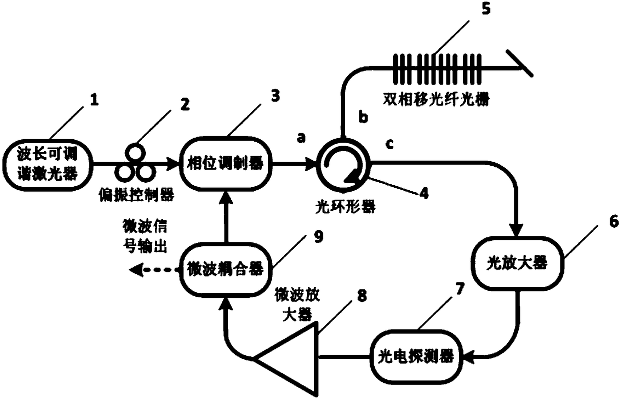
[0028] Such as figure 1 As shown, a thermally stable sensing and demodulation system using narrowband dual phase-shift fiber gratings, including: wavelength tunable laser 1, polarization controller 2, phase modulator 3, optical circulator 4, dual phase-shift fiber grating 5 , optical amplifier 6, photodetector 7, microwave amplifier 8, microwave coupler 9;

[0029] The wavelength tunable las...


PUM


Abstract

The invention provides a thermal stability sensing demodulation system and method using a narrowband dual phase shift fiber bragg grating. The system comprises a wavelength tunable laser, a polarization controller, a phase modulator, a three-port optical circulator, a dual-phase-shift fiber bragg grating, an optical fiber amplifier, a photoelectric detector, a microwave amplifier and a microwave coupler which are mutually connected. The first port of the optical circulator is connected to the output port of the phase modulator. The second port of the optical circulator is connected to the dual-phase-shift fiber bragg grating. The third port of the optical circulator is connected to the optical fiber amplifier. The input end of the microwave coupler is connected to the output end of the microwave amplifier. The first output end of the microwave coupler is connected to the radio frequency end of the phase modulator. The second output end of the microwave coupler is connected to an electric spectrometer.

Description

technical field [0001] The invention relates to the field of microwave photons generated by microwave signals and the field of fiber grating sensing, more specifically, to a system and method for thermally stable sensing and demodulation using narrow-band dual-phase-shift fiber gratings. Background technique [0002] Optical fiber sensing technology has many advantages such as anti-electromagnetic interference, anti-chemical corrosion, intrinsic safety, high / low temperature resistance, small size, light weight, softness and flexibility, etc., and has been used in aerospace, civil engineering, power systems, petrochemical, medical and health , home security and other fields have been widely and important applications. [0003] As an important optical device in fiber optic sensing technology, fiber Bragg grating has always been a hot spot for researchers. Fiber Bragg grating sensors have wavelength encoding characteristics for sensing information, also known as wavelength mod...

Claims


Application Information

Patent Timeline
Patent Type & Authority Applications(China)
IPC IPC(8): G01D5/26G01D5/34
CPCG01D5/268G01D5/34
Inventor 许鸥韩一石骆德汉
Owner GUANGDONG UNIV OF TECH
Learn More