Grading cold accumulation type supercritical compressed air energy storage system and method
A technology of compressed air energy storage and supercritical air, which is applied in the direction of engine function, household refrigeration equipment, steam engine equipment, etc., and can solve the problems of large-scale, low-cost, safe and reliable energy storage, insufficient cold energy recovery, etc.
- Summary
- Abstract
- Description
- Claims
- Application Information
AI Technical Summary
Problems solved by technology
Method used
Image
Examples
Embodiment 1
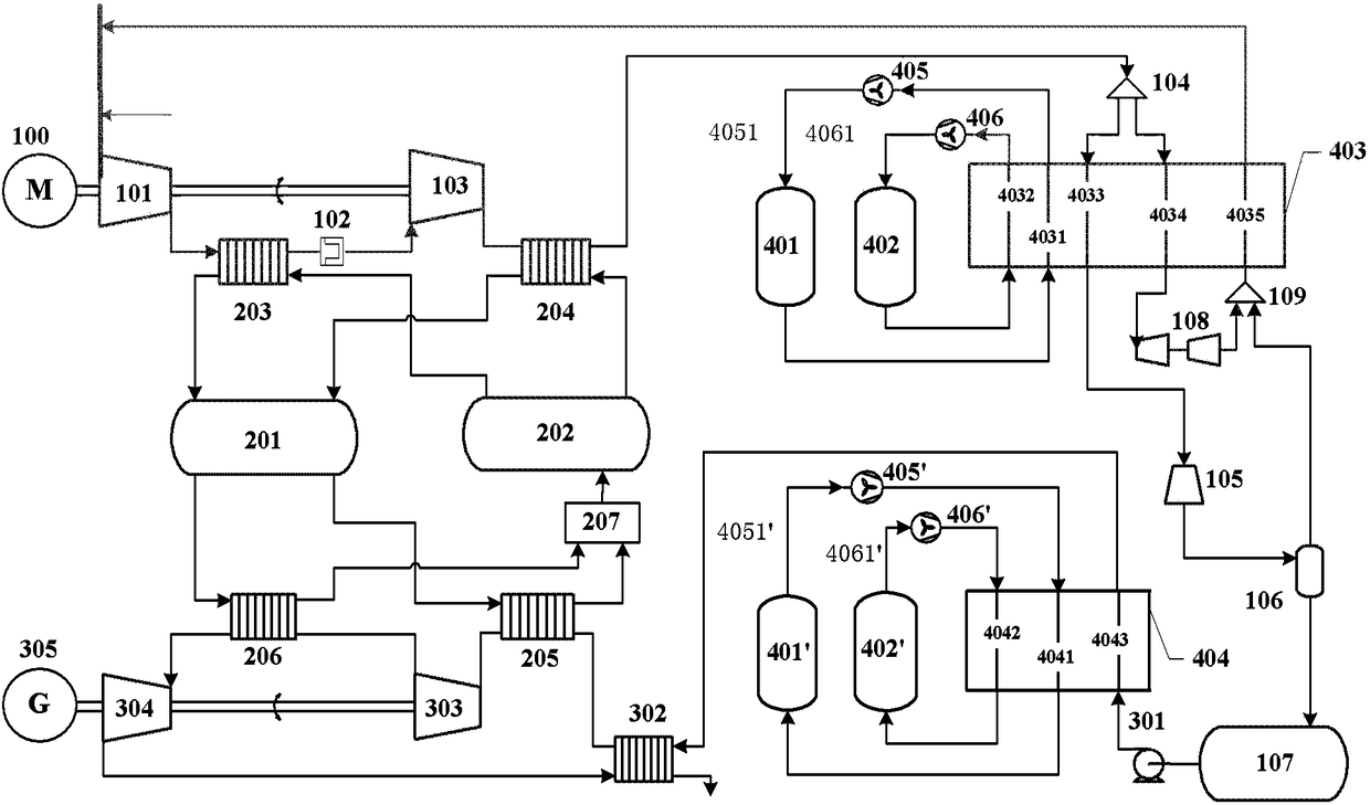
[0183] figure 2 It is a schematic diagram of a hierarchical cold storage type supercritical compressed air energy storage system combined with a single cryogenic cold storage cycle and an intercooler storage tank according to a specific embodiment of the present invention.
[0184] In this embodiment, the working fluid is heat transfer oil, the compressor is two-stage compression, and the expander is two-stage expansion, using a single heat storage tank, a single normal temperature tank, a single low-temperature liquid storage tank, and a single graded cold storage subsystem; wherein, the graded The cold storage subsystem includes a single cryogenic storage tank, a single intercooling storage tank, a single liquefied cold box, and a single evaporative cold box. The waste heat utilization device is an absorption refrigeration unit, and the low-temperature expander is a two-stage expansion. Atmospheric pressure. The gas returned by the cold energy recovery channel 4035 of the ...
Embodiment 2
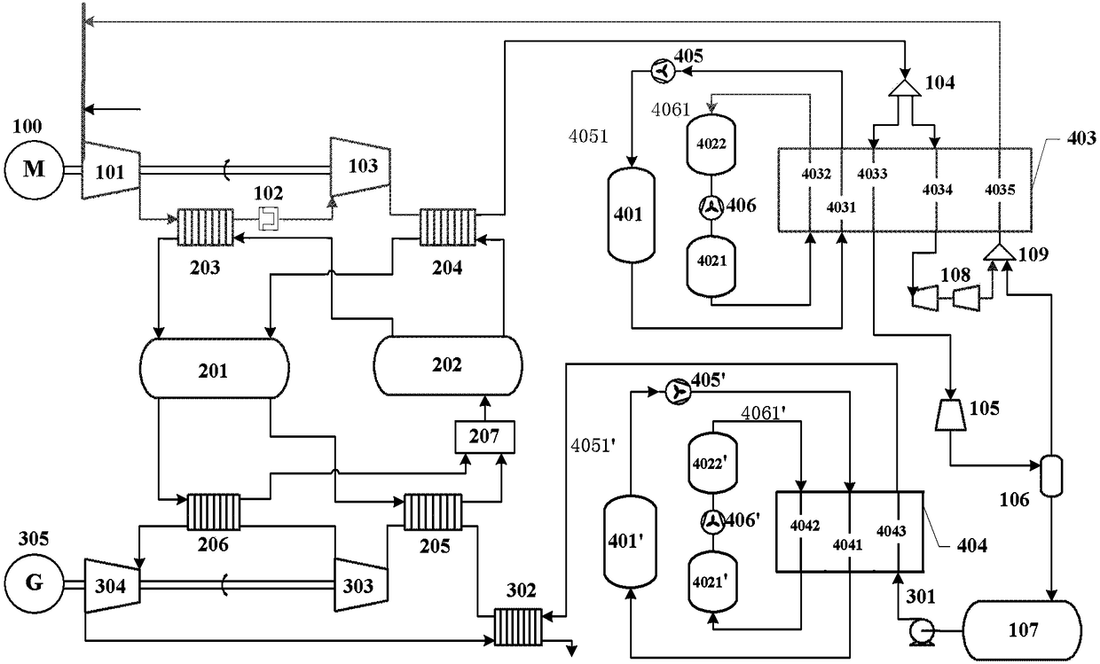
[0194] image 3 It is a schematic diagram of a hierarchical cold storage type supercritical compressed air energy storage system in which the intercooler storage tank is a double-tank series structure in a specific embodiment of the present invention; image 3 As shown, the improvement relative to Embodiment 1 is: when at least one intercooler storage tank is two intercooler storage tanks, the lower intercooler storage tank 4021 and the upper intercooler storage tank 4022 are connected in series, and the lower intercooler storage tank 4021 stores the Cold energy from cold to normal temperature The upper intercooler storage tank 4022 stores cold energy from deep cooling to normal temperature, and the normal temperature sides of the lower intercooler storage tank 4021 and the upper intercooler storage tank 4022 are connected through the intercooler circulation fan 406, and the The advantage is that the intercooling circulating fan 406 can operate at normal temperature, avoiding ...
Embodiment 3
[0197] Figure 4 It is a schematic diagram of a graded cold storage type supercritical compressed air energy storage system under a higher pressure of a cryogenic liquid storage tank according to a specific embodiment of the present invention; Figure 4 As shown, the improvement relative to Implementation 1 is: the low-temperature and normal-pressure gas returned from the cold energy recovery channel 4035 of the liquefied cold box returns to the gas path between the drying and purification device 102 and the final compressor, instead of returning to the inlet of the primary compressor 101 . At this time, the pressure of the liquid air stored in the low-temperature heat-insulated storage tank 107 is not close to the normal pressure, but much higher than the normal pressure.
[0198] In the energy storage stage, the supercritical fluid in the cold energy compensation channel 4034 of the liquefied cold box absorbs part of the cold energy and cools down, then expands through the ...
PUM
 Abstract
Description
Claims
Application Information
 - R&D
- Intellectual Property
- Life Sciences
- Materials
- Tech Scout
- Unparalleled Data Quality
- Higher Quality Content
- 60% Fewer Hallucinations
Browse by: Latest US Patents, China's latest patents, Technical Efficacy Thesaurus, Application Domain, Technology Topic, Popular Technical Reports.
© 2025 PatSnap. All rights reserved.Legal|Privacy policy|Modern Slavery Act Transparency Statement|Sitemap|About US| Contact US: help@patsnap.com


