
Multi-pollutant cooperative control system for flue gas and water collection technology thereof

A technology for collaborative control and pollutants, applied in the direction of gas treatment, climate sustainability, greenhouse gas reduction, etc., to achieve the effect of reducing specific heat, improving governance level, and reducing operating costs

Pending Publication Date: 2018-12-11
杭州蕴泽环境科技有限公司
View PDF5 Cites 7 Cited by
  • Summary
  • Abstract
  • Description
  • Claims
  • Application Information

AI Technical Summary

Problems solved by technology

[0004] At present, for the deep coordinated control of multi-pollutants in wet desulfurization tail gas, the technology and equipment for recovering water resources in tail gas to realize near-zero emission of desulfurization tail gas are still blank

Method used


Image

  • Multi-pollutant cooperative control system for flue gas and water collection technology thereof

Examples


Embodiment 1

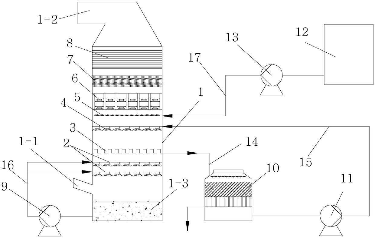
[0020] Embodiment 1: refer to figure 1 . A flue gas multi-pollutant cooperative control system, including a desulfurization tower 1 with a flue inside, and in the desulfurization tower 1, from bottom to top, at least one set of desulfurization spray layer 2, cooling liquid accumulation layer 3, and cooling spray Layer 4, mist eliminator, flue gas heat exchange layer 8; a smoke inlet 1-1 is arranged on the side wall of the lower end of the desulfurization tower 1, and a smoke outlet 1-2 is arranged on the top or the top side of the desulfurization tower 1. A desulfurization circulation pump 9, a circulating fluid cooling tower 10, a condensation cooling circulation pump 11, and a demister flushing pump 13 are provided outside the desulfurization tower 1. The other end of the pipeline 14 is connected to the liquid return port of the circulating liquid cooling tower 10, and the liquid outlet at the bottom of the circulating liquid cooling tower 10 is connected to the liquid supp...

Embodiment 2

[0031] Embodiment 2: refer to figure 1 . A water collection method for a flue gas multi-pollutant collaborative control system, comprising the following process steps through the flue gas multi-pollutant collaborative control system:

[0032] 1) The sulfur-containing flue gas enters the absorption tower 1 from the inlet flue, and performs a reverse contact reaction with the desulfurization liquid sprayed from the desulfurization spray layer 2 to remove most of the SO in the original flue gas 2 , HF, HC l Such as acid gas and dust particles, the flue gas is cooled to 50°C-60°C and reaches saturation;

[0033] 2) The high-humidity saturated flue gas containing many pollutants flows upward into the cooling condensation layer, and conducts reverse contact and heat exchange with the circulating slurry in the lower temperature cooling spray layer 4. The temperature of the flue gas drops to 30-45°C, and the saturated steam Cooling and condensing, a large amount of water vapor and ...

Embodiment 3

[0038] Example 3. In a thermal power plant, the flue gas desulfurization renovation project of a 300WM unit adopts this process. The SO2 concentration in the inlet flue gas is 2239mg / m3, the dust concentration in the inlet flue gas is 45mg / m3, and the liquid-gas ratio of the cooling spray layer circulating fluid is 2.3 L / Nm3, the coverage rate of the spray layer is 200%, the gas-liquid contact time is 1.2s, the flue gas cooling range is 13°C, the height of the liquid accumulation layer from the top desulfurization spray layer is 0.5, and the distance between the liquid accumulation layer and the cooling spray layer The distance of the demister is 2m, the preparation pressure of the ultra-fine atomization nozzle for flushing the spray layer of the mist eliminator is 0.12MPa, the flushing liquid-gas ratio is 0.05L / Nm3, and the flue gas cooling range is 1.8°C. The SO2 concentration in the outlet flue gas is 2.7mg / m3, the dust concentration in the outlet flue gas is 0.6mg / m3, and ...


PUM


Abstract

The invention relates to a multi-pollutant cooperative control system for flue gas and a water collection technology thereof. The multi-pollutant cooperative control system for the flue gas comprisesa desulfurization tower arranged in a flue, wherein the desulfurization tower is internally provided with one or more group of desulfurization spraying layer, a cooling and liquid deposition layer, acooling and spraying layer, a demister and a flue gas heat exchange layer in sequence from bottom to top; a cooling liquid pipeline communicated and connected with the cooling and liquid deposition layer is arranged outside the desulfurization tower; the other end of the cooling liquid pipeline is communicated and connected with a liquid returning opening of a circulating liquid cooling tower; a bottom liquid outlet of the circulating liquid cooling tower is communicated and connected with a liquid supply pipe of the cooling and spraying layer through a first circulating pipeline which is connected with a condensing and cooling circulating pump in series; a second circulating pipeline which is connected with a desulfurization circulating pump in series and is communicated with a desulfurization slurry tank is arranged outside the desulfurization tower; the other end of the desulfurization tower is communicated and connected with each desulfurization and spraying layer. By adopting themulti-pollutant cooperative control system, deep cooperative control can be carried out on a plurality of pollutants in wet-process desulfurization tail gas; near zero emission of the plurality of pollutants is realized and water in wet flue gas is recycled; the system can also be used for deep treatment of other high-humidity flue gas.

Description

technical field [0001] The invention relates to the technical fields of chemical industry and environmental protection, in particular to a flue gas multi-pollutant cooperative control system and a water collection process thereof. Background technique [0002] At present, 100% of the flue gas from thermal power coal-fired boilers in my country has been sent to desulfurization devices, and more than 90% of them have adopted limestone-gypsum wet flue gas desulfurization technology. During the operation of the coal-fired boiler wet desulfurization device, a large amount of water is brought out by the exhaust gas of the desulfurization tail gas. Taking a 300MW unit as an example, the desulfurization system consumes 120m water per hour 3 / h, including 71.8m moisture in the original flue gas 3 / h, desulfurization system make up water 40m 3 / h, based on the annual operating time of 8000 hours, the annual water consumption of a 300MW unit is 1 million tons. Discharge flue gas 100...

Claims


Application Information

Patent Timeline
Patent Type & Authority Applications(China)
IPC IPC(8): B01D53/75B01D53/80B01D53/40B01D53/96B01D53/00B01D53/26B01D47/06F23J15/06
CPCB01D47/06B01D53/002B01D53/26B01D53/40B01D53/75B01D53/80B01D53/96F23J15/06B01D2258/0283B01D2257/302B01D2257/2045B01D2257/2047Y02E20/30
Inventor 程磊俞钱永关向军
Owner 杭州蕴泽环境科技有限公司
Learn More