
Optical path converging structure

A technology of optical path and converging lens, which is applied in color/spectral characteristic measurement, material analysis through optical means, measuring device, etc. It can solve the problems of insufficient light intensity, low utilization rate of reflective mirror surface, etc., and achieve accurate smoke concentration Detection effect

Pending Publication Date: 2018-12-07
ANHUI AGRICULTURAL UNIVERSITY
View PDF2 Cites 2 Cited by
  • Summary
  • Abstract
  • Description
  • Claims
  • Application Information

AI Technical Summary

Problems solved by technology

[0007] The present invention provides an optical path converging structure, the purpose of which is to solve the problem of insufficient light intensity in the existing way of using absorption spectrum to detect smoke concentration
The light path converging structure converges the light through a reasonable combination of collimating mirrors, converging lenses and beam splitters to form a high-power coaxial beam, which overcomes the insufficient light intensity of a single luminous tube in the prior art and the lack of brightness of multiple luminous tubes. The problem that the emitted light is not on the same axis and the light intensity is not enough
[0008] The present invention provides another optical system for smoke detection, the purpose of which is to solve the problems of insufficient light intensity, low utilization rate of reflecting mirrors, and large spectral errors in the existing method of smoke concentration detection using absorption spectrum.

Method used


Image

  • Optical path converging structure
  • Optical path converging structure
  • Optical path converging structure

Examples


Embodiment

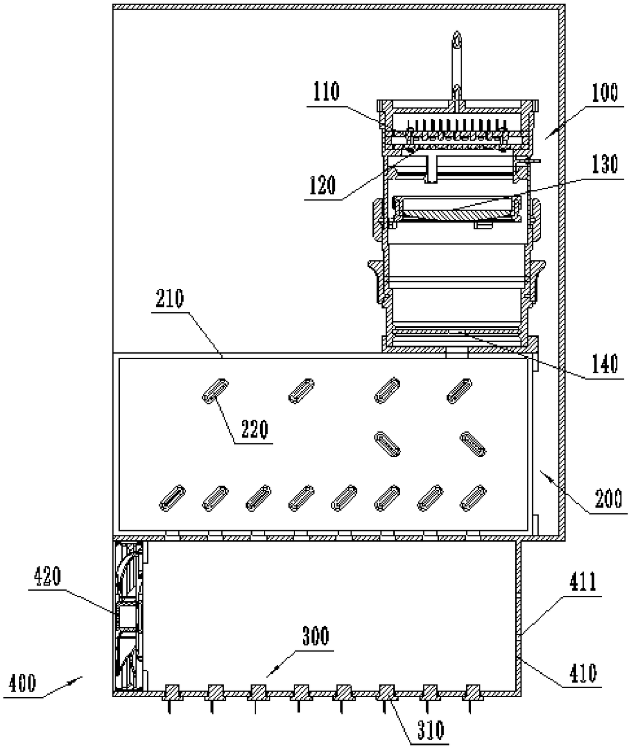
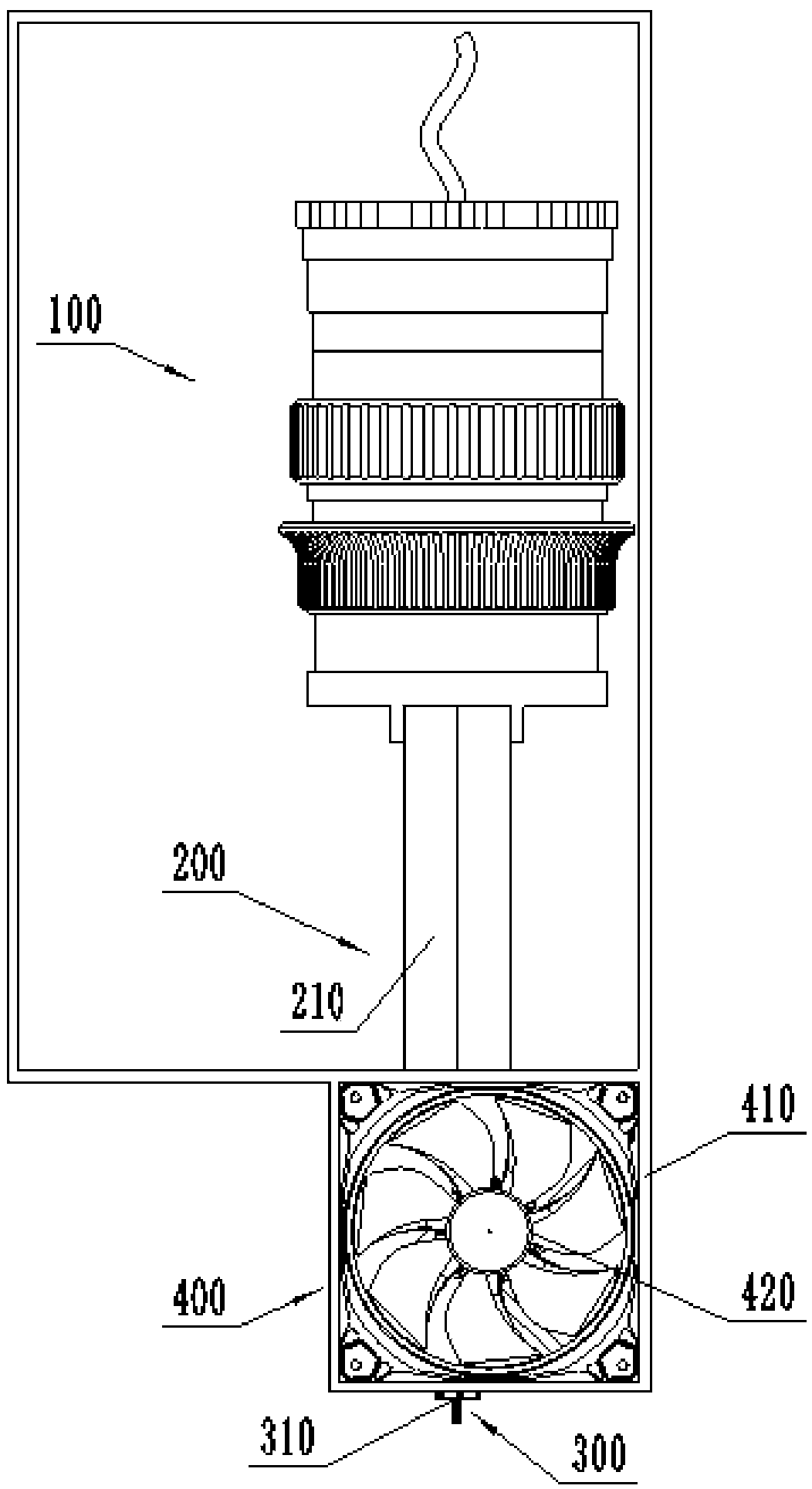
[0056] Such as figure 1 , figure 2 As shown, this embodiment provides an optical system for smoke detection, which mainly uses optical principles to detect smoke concentration. The detection part 300. Wherein, the light source part 100 is mainly used for converging the more scattered and weaker light emitted by the light source to form a more concentrated and stronger light beam to increase the light intensity of the light source; the light splitting part 200 is used for converging the light source part 100 The light beam is divided into multiple light beams with basically the same light intensity; the flue gas channel part 400 can pass through the flue gas, and the passing flue gas can be passed by the multiple light beams separated by the light splitting part 200, so that the flue gas can absorb part of the light; The detection part 300 is used to receive the light beam passing through the smoke, and detect the absorption spectrum to perform smoke detection. The whole sy...


PUM


Abstract

The invention discloses an optical path converging structure, and belongs to the technical field of gas smoke intensity detection. The optical path converging structure comprises a light source part,wherein the light source part comprises a light emitting element, a primary alignment mirror, a converging lens and a secondary alignment mirror which are sequentially arranged along the lighting direction of a light-emitting component; the light source part further comprises a light source support cylinder, an intermediate cylinder and a lower cylinder which are connected end to end sequentiallyfrom top to bottom; the light-emitting component and the primary alignment mirror are arranged in the light source support cylinder in up-down direction; the converging lens is arranged in the intermediate cylinder; and the secondary alignment mirror is arranged in the lower cylinder. According to the optical path converging structure, light is converged by reasonably combining the alignment mirrors, the converging lens and a beam splitter to form a high power coaxial light beam, and the problems a single light emitting tube does not have sufficient light intensity or brightness, but lights emitted from a plurality of light emitting tubes are not on the same axes and do not have sufficient light intensity in the prior art can be solved.

Description

technical field [0001] The invention belongs to the technical field of gas smoke detection, and relates to an optical path converging structure, and more specifically, to a smoke detection optical system and a method thereof. Background technique [0002] With the development of the world economy, environmental pollution is becoming more and more serious, and the detection and treatment of air quality has become the focus of attention. The technology of using spectral characteristics to analyze atmospheric components has been widely used in the fields of atmospheric trace gas detection, industrial process control, and emission monitoring of urban pollution sources. Therefore, it is of great significance to develop devices that can accurately and real-time measure air gas concentrations. [0003] In order to improve the detection sensitivity of absorption spectroscopy to low-concentration gases, increasing the length of the light beam passing through the gas sample is an effe...

Claims


Application Information

Patent Timeline
IPC IPC(8): G01N15/06G01N21/01G01N21/31
CPCG01N15/06G01N21/01G01N21/31G01N2021/0112G01N15/075
Inventor 刘路廖娟孙燕陈黎卿高观光李亚伟
Owner ANHUI AGRICULTURAL UNIVERSITY
Learn More