
A kind of electromagnetic separation device of shell support of light gas gun

A technology of electromagnetic separation and light gas gun, which is applied in the direction of compressed air guns, weapons without explosives, offensive equipment, etc. It can solve the problems of limited projectile velocity range, insufficient separation, limited container size, etc., and achieve the effect of improving controllability

Active Publication Date: 2020-04-17
BEIJING INSTITUTE OF TECHNOLOGYGY
View PDF8 Cites 0 Cited by
  • Summary
  • Abstract
  • Description
  • Claims
  • Application Information

AI Technical Summary

Problems solved by technology

Although the pneumatic separation technology avoids the influence of the impact force on the projectile when intercepting the projectile support, the gas in the container will also affect the projectile velocity
When the launch speed of the projectile is high, the flight time of the projectile in the container is shortened. Only by filling a higher pressure gas can the complete separation of the projectile and the projectile support be ensured in a shorter time. Due to the limitation of the sealing diaphragm, the container is filled with The pressure of the gas is limited
At the same time, the size of the container is limited, so that the flight time of the projectile inside is short, and the separation will be insufficient at high speed, which limits the range of projectile velocity applicable to the pneumatic separation technology.

Method used


Image

  • A kind of electromagnetic separation device of shell support of light gas gun
  • A kind of electromagnetic separation device of shell support of light gas gun
  • A kind of electromagnetic separation device of shell support of light gas gun

Examples


Embodiment Construction

[0018] The present invention will be described in detail below with reference to the accompanying drawings and examples.

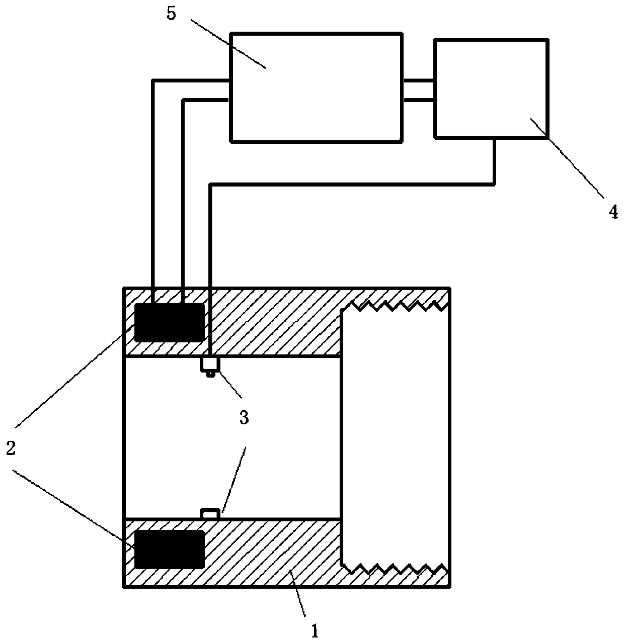
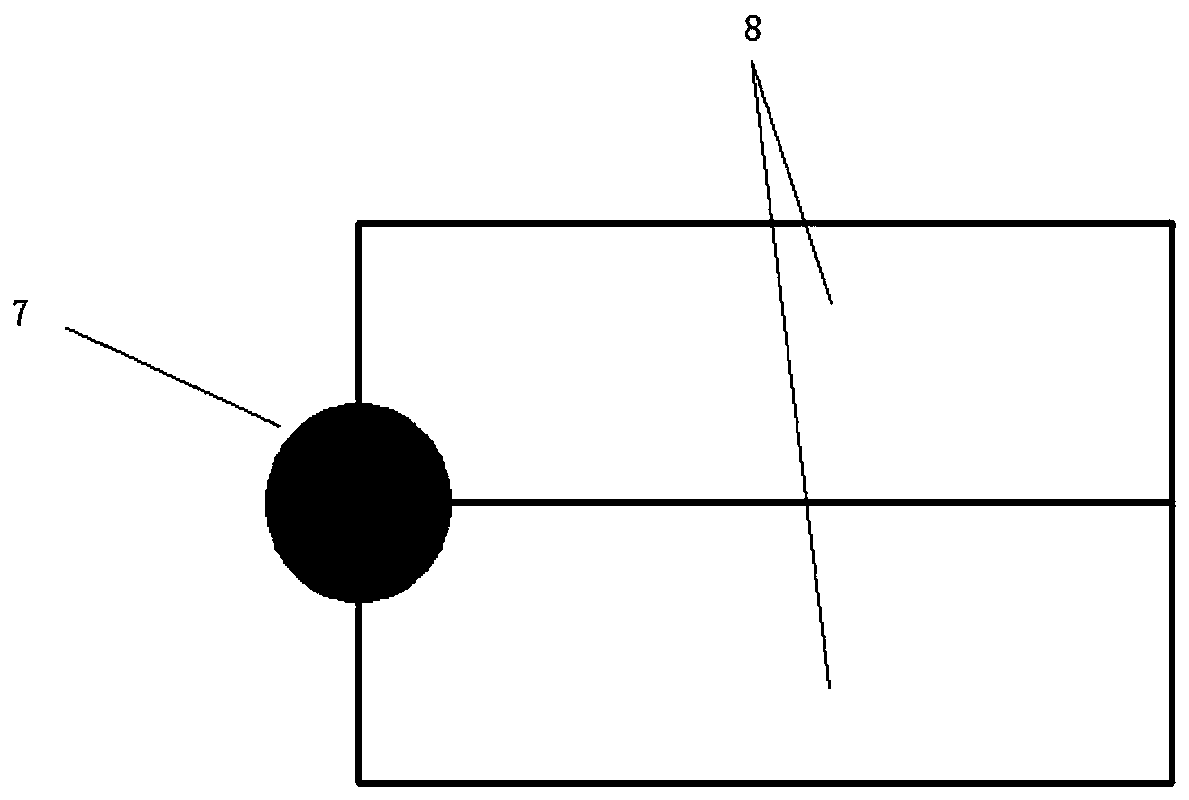
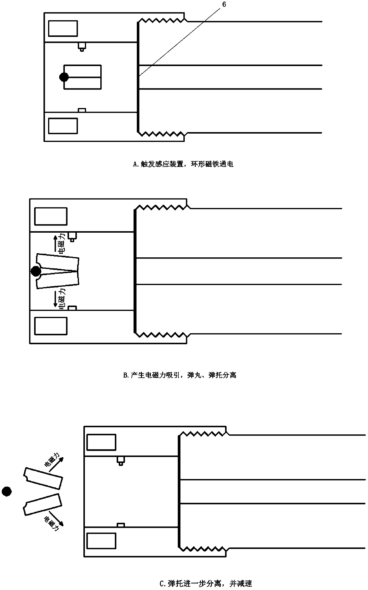
[0019] See attached figure 1 , an electromagnetic separation device for a light gas gun, comprising: an annular shell 1 with a set wall thickness, an annular electromagnet 2, an induction device 3, a controller 4, and a storage device 5;

[0020] One end of the annular housing 1 is provided with a thread suitable for the muzzle of the light gas gun, and the annular housing 1 is threadedly connected with the muzzle 6 of the light gas gun at this end, so that the electromagnetic separation device is installed on the light gas gun. There are 6 muzzles; the other end of the annular housing 1 is provided with an annular electromagnet 2; the induction device 3 in this example adopts a laser trigger, and the laser trigger is installed on the inner peripheral surface of the annular housing 1 , located between the ring electromagnet 2 and the muzzle 6; the laser t...


PUM


Abstract

The invention relates to the technical field of hypervelocity impact loading tests, in particular to a sabot separation device. The electromagnetic sabot separation device for a light-gas gun comprises an annular casing, annular electromagnets, a sensing device, a controller and an electric storage device, wherein a projectile and the sabot are accelerated by the light-gas gun to enter an electromagnetic separation device connected with a gun muzzle, and when the projectile and the sabot pass through the sensing device located on the inner wall of the electromagnetic separation device, the sensing device triggers the controller to control the electric storage device to produce strong current to power on the annular electromagnets and the annular electromagnets produce strong attraction force on the sabot made of a ferromagnetic high-polymer material. The sabot with a split structure is separated towards the lateral direction under the action of uneven electromagnetic attraction force,and meanwhile, after the sabot flies over the positions of the electromagnets, the annular electromagnets produce backward electromagnetic force on the sabot to slow down the sabot, so that the sabotand the projectile are separated. The sabot is separated from the projectile stably and smoothly without impact.

Description

technical field [0001] The invention relates to the technical field of ultra-high-speed impact loading tests, in particular to a bullet holder separation device. Background technique [0002] Researches on spacecraft protection, kinetic energy weapons, and high-pressure physics all require ultra-high-speed launch technology. Compared with other firing techniques, the light gas cannon is a particularly versatile device because it can fire a variety of projectile shapes, with a wide range of projectile masses, sizes and materials. Light gas gun is a device that uses light compressed gas to accelerate projectiles. There are first-level light gas guns, second-level light gas guns and third-level light gas guns. The first-level light gas gun can load larger mass projectiles to 0.5-2km / s, the second-level light gas gun can load the projectile with a smaller mass to 2-7km / s, and the third-level light gas gun can load the projectile to more than 10km / s. It can be used to simulate...

Claims


Application Information

Patent Timeline
Patent Type & Authority Patents(China)
IPC IPC(8): F41B11/70
CPCF41B11/70
Inventor 任思远张庆明薛一江龙仁荣龚良飞
Owner BEIJING INSTITUTE OF TECHNOLOGYGY
Learn More