Dispensing roller, dispensing device and dispensing system
A technology of dispensing device and roller, which is applied to devices and coatings that apply liquid to the surface, can solve the problems of bumping and overflowing during the panel lamination process, and achieve the effect of preventing bumps, reducing accumulation and being easy to achieve.
- Summary
- Abstract
- Description
- Claims
- Application Information
AI Technical Summary
Problems solved by technology
Method used
Image

Examples
Embodiment 1
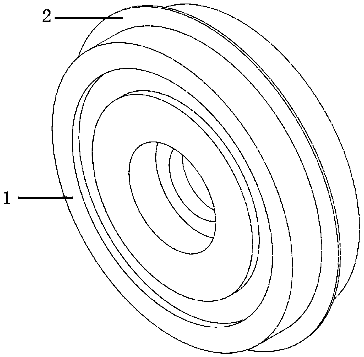
[0052] This embodiment provides a dispensing roller, such as figure 1 As shown, a roller body 1 is included, and an annular protrusion 2 protrudes from the outer wall surface of the roller body 1 .
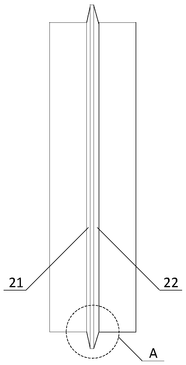
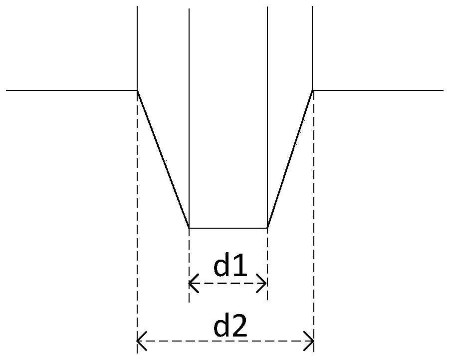
[0053] Such as figure 2 As shown, the annular protrusion 2 includes a first end close to the roller body 1 and a second end far away from the roller body 1 , that is, the first end is opposite to the second end. in, image 3 show figure 2 In the enlarged view of part A, the axial width d2 of the first end face is greater than the axial width d1 of the second end face.
[0054] Please refer to figure 2 , the sidewall surface of the annular protrusion 2 in its radial direction is a first inclined surface 21, and the first inclined surface 21 is inclined outward from the second end toward the first end; The other side wall surface in the direction is a second inclined surface 22, which is inclined outward from the second end toward the first end.
[0055] The inclination ang...
Embodiment 2
[0062] This embodiment provides a dispensing device, such as Figure 4 As shown, it includes the dispensing roller, the glue supply mechanism 4, the support mechanism 3 and the recovery device in Embodiment 1. For the relevant structural details of the dispensing roller in this embodiment, please refer to Embodiment 1, which will not be repeated here.
[0063] The glue supply mechanism 4 includes a housing 41 and a driving member (not shown in the figure). Wherein, the housing 41 has a cavity for containing glue, and a glue outlet (not shown in the figure) opened on the side wall facing the radially outer surface of the annular protrusion 2 on the outer peripheral wall of the roller. Preferably, the colloid stored in the cavity is a low-precision colloid. Since the low-precision colloid has better adhesion and low cost, the cost of dispensing can be saved.
[0064] Such as Figure 5 As shown, there is an installation step 42 on the outer wall of the housing 41 , and a scrap...
Embodiment 3
[0078] This embodiment provides a dispensing system, such as Figure 6 As shown, the dispensing device and the rotating platform in Embodiment 2 are included.
[0079] Such as Figure 7 As shown, the dispensing system is installed on the installation platform, which is composed of upper and lower parts of the box. The electrical control system of the dispensing device is packaged inside the upper box body 71 , the dispensing device is installed on the outer surface of the upper box body 71 , and the rotating platform is used to realize dispensing of the screen body 62 . The lower box body 72 is used as a reserved space to lay the foundation for later transformation. For the details of the relevant components of the dispensing device in this embodiment, please refer to Embodiment 2, which will not be repeated here.
[0080] Such as Figure 6 As shown, the rotating platform in this embodiment is used to drive the screen body 62 to rotate, thereby indirectly driving the dispe...
PUM
| Property | Measurement | Unit |
|---|---|---|
| angle | aaaaa | aaaaa |
Abstract
Description
Claims
Application Information
 - R&D
- Intellectual Property
- Life Sciences
- Materials
- Tech Scout
- Unparalleled Data Quality
- Higher Quality Content
- 60% Fewer Hallucinations
Browse by: Latest US Patents, China's latest patents, Technical Efficacy Thesaurus, Application Domain, Technology Topic, Popular Technical Reports.
© 2025 PatSnap. All rights reserved.Legal|Privacy policy|Modern Slavery Act Transparency Statement|Sitemap|About US| Contact US: help@patsnap.com