Rotating direction conversion mechanism of cutter assembly of front mounted ditching machine

A technology of rotating direction and switching mechanism, which is applied in the direction of tillage implements, agricultural machinery and implements, etc. It can solve problems such as easy blockage, heavy ditching machine load, and inconvenient operation.

Pending Publication Date: 2018-12-07
田开林
View PDF10 Cites 1 Cited by
  • Summary
  • Abstract
  • Description
  • Claims
  • Application Information

AI Technical Summary

Problems solved by technology

[0005] Most of the patents on trenchers disclosed in the prior art are rear-mounted structures. Although the rear-mounted trencher can realize ditching, the actual operation of the trencher is always inconvenient. When targeting a large area There are always laborious situations in farmland ditching operation, and there are always problems of inconvenient operation and low efficiency in actual ditching operation
[0006] In order to solve the existing problems, the applicant applied for a patent application titled "Front Type Ditching Machine" on the same day. The ditching machine was installed on the front end of the four-wheel tractor, so as to effectively improve the convenience of ditching operation and improve the efficiency of ditching. Ditch efficiency, when the above-mentioned front-mounted ditching machine is actually used, when the ditching tool assembly is performing ditching operation, soil residue and vegetation will spin backwards, which will easily cause blockage, resulting in excessive load on the ditching machine

Method used


Image

  • Rotating direction conversion mechanism of cutter assembly of front mounted ditching machine
  • Rotating direction conversion mechanism of cutter assembly of front mounted ditching machine
  • Rotating direction conversion mechanism of cutter assembly of front mounted ditching machine

Examples


Embodiment Construction

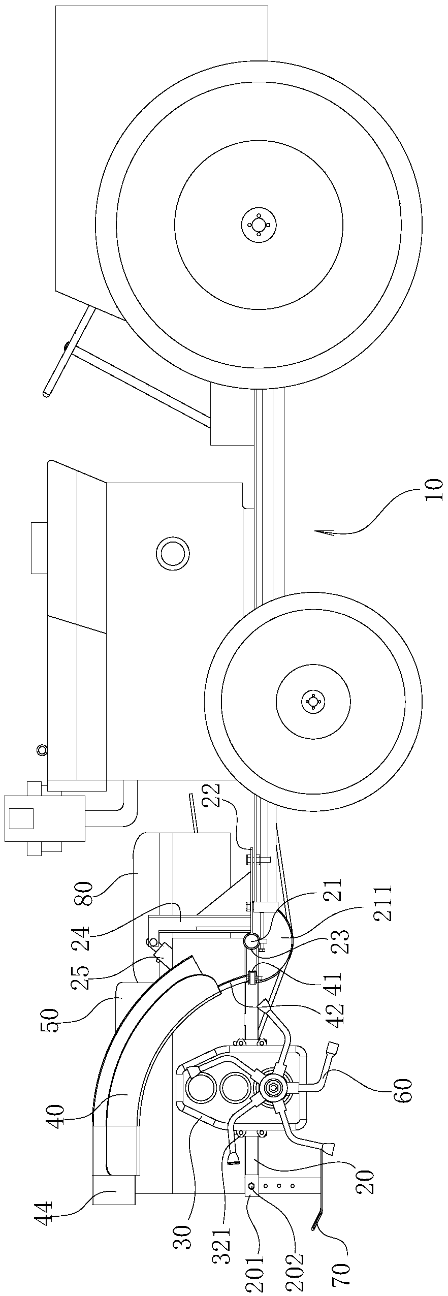
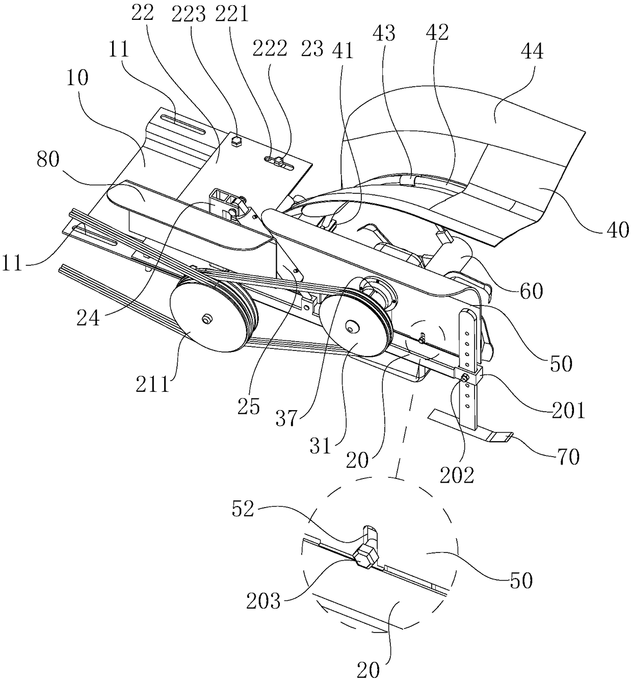
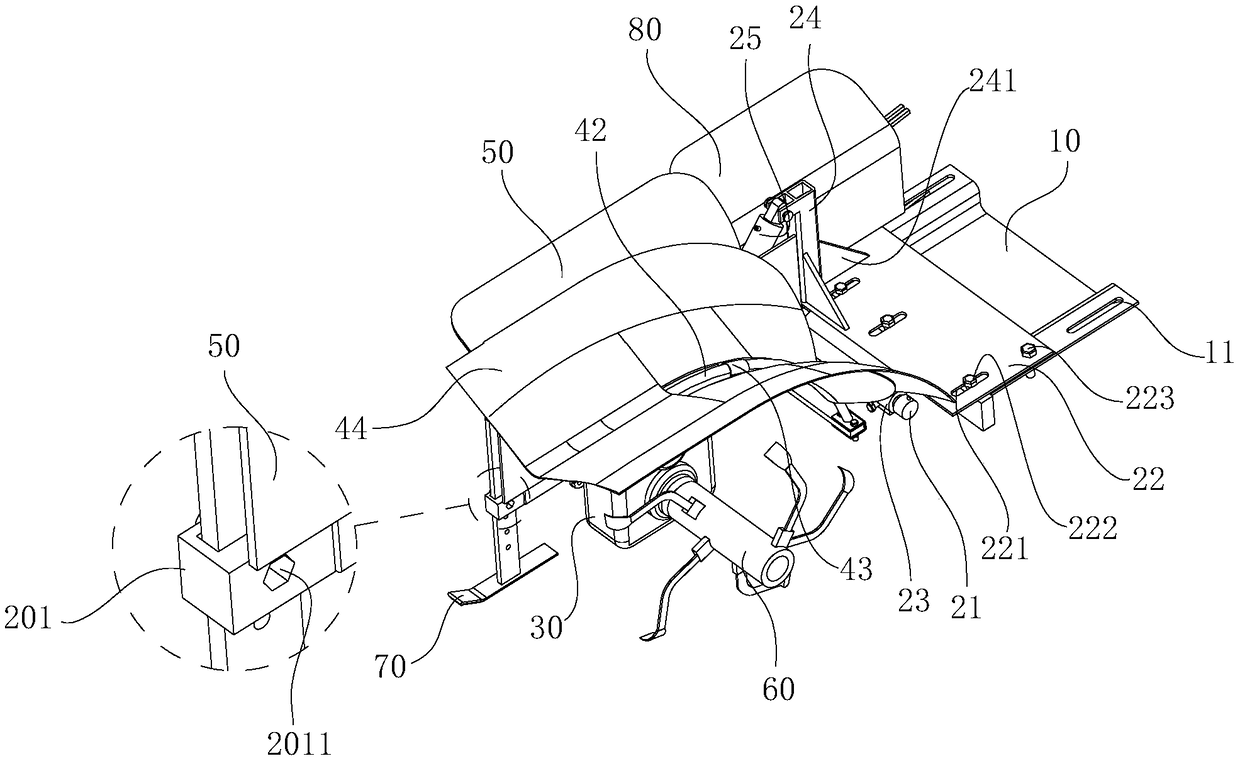
[0021] refer to Figure 1 to Figure 7 , the characteristics of the tool assembly rotation direction conversion mechanism of this front-mounted ditching machine are described in detail as follows:

[0022] The following is a detailed description of the tool assembly rotation direction conversion mechanism of the front-mounted ditcher of the present invention in conjunction with the entire front-mounted ditcher:

[0023] The front-mounted ditching machine includes a frame 20 hingedly connected to the front end of the four-wheel tractor 10, the hinge axis of the frame 20 is horizontal and the length direction is perpendicular to the vehicle length direction of the four-wheel tractor 10, and the frame 20 is provided with There is a gearbox 30, the input shaft of the gearbox 30 is connected with the driving wheel of the four-wheel tractor 10 through a transmission mechanism, the output shaft of the gearbox 30 is provided with a ditching tool assembly 60, and the four-wheel tractor ...


PUM


Abstract

The invention relates to a rotating direction conversion mechanism of cutter assembly of a front mounted ditching machine, which comprises a gearbox, wherein the gearbox comprises a box body. An inputgear, a transition gear and an output gear are rotatably arranged in the box body. The input gear meshes with the transition gear, and the transition gear meshes with the output gear. An input shaftis arranged at the input gear, and an output shaft is arranged at the output gear. A ditching cutter assembly is arranged at the output shaft. The gearbox comprises three gears, which can not only adjust rotating speed of the ditching cutter assembly, but also change the rotating direction of the ditching cutter assembly, so that the tangential direction of the ditching cutter assembly and the ground is oriented toward the front end of the long side of the four-wheel tractor, so as to achieve ditching operation, prevent soil residue, weeds and branches from falling out behind the four-wheel tractor, and avoid the occurrence of blockage or flame out caused by excessive load of the ditching cutter assembly.

Description

technical field [0001] The invention relates to the technical field of agricultural machinery, in particular to a tool assembly rotation direction conversion mechanism of a front ditching machine. Background technique [0002] The trencher can be used in construction engineering to dig narrow and deep underground trenches to bury underground drainage pipes, or to bury cables and pipelines in railway, post and telecommunications, urban construction and other departments, and can also be used in orchards, vegetable gardens, and other farmland environmental development. Ditch fertilization, drainage, planting, irrigation. [0003] Existing small-sized ditchers that are used for farmland ditching mostly are installed on the walking tractor. The patent titled "Rear Left Side Ditcher" (Patent No.: 201310743234.0) discloses a rear left side ditcher structure, the ditcher is directly connected to the rear connection frame of the walking tractor. The L-shaped frame is equipped with...

Claims


Application Information

Patent Timeline
IPC IPC(8): A01B33/08
CPCA01B33/082
Inventor 田开林田超
Owner 田开林
Why Eureka
Try Eureka