
Data center network fault node diagnosis method and system based on dialing test data

A technology of data center network and faulty nodes, applied in the field of supervision, can solve problems such as increased controller overhead, increased network load, and large time complexity of probe paths, and achieves the effect of reducing computing overhead and improving performance.

Active Publication Date: 2018-12-04
XIDIAN UNIV
View PDF2 Cites 12 Cited by
  • Summary
  • Abstract
  • Description
  • Claims
  • Application Information

AI Technical Summary

Problems solved by technology

2) Increased network load: The data center can greatly reduce the algorithm execution time, but it will also lead to the possibility of increased controller overhead
This technique is simple but has two obvious disadvantages: 1) its threshold is chosen empirically; 2) data below the threshold is not analyzed, resulting in some details related to network conditions may be missed
[0005] (2) Active fault diagnosis is limited by traffic overhead in large-scale networks, and it is necessary to place reasonable and effective detection base stations in the network. The location and number of detection base stations directly affect the accuracy of fault diagnosis results, but existing research has not Problems with probing base stations and quantities
Moreover, in a large-scale network, the design of the probe path of the overlay network has a great time complexity. When the network topology changes, it needs to be recalculated, which is not suitable for dynamic network structures.
[0006] (3) In the technology based on the network system log, the decision threshold is selected based on experience; on the one hand, because the technology does not analyze the data below the threshold, some detailed information related to the network status may be missed
For large-scale and complex networks, it is an NP-hard problem to solve the problem of sending probes to traverse the network path once. Every time the network changes, it needs to be recalculated. There are great limitations in network topology reconstruction and optimization, so looking for a A new reasonable and effective fault diagnosis mode is very necessary in engineering
On the other hand, when judging whether a network node is faulty, the traditional method relying on human experience also has great limitations. Therefore, it is of great research significance to establish a suitable model and select a suitable threshold for different network structures.

Method used


Image

  • Data center network fault node diagnosis method and system based on dialing test data
  • Data center network fault node diagnosis method and system based on dialing test data
  • Data center network fault node diagnosis method and system based on dialing test data

Examples


example 1

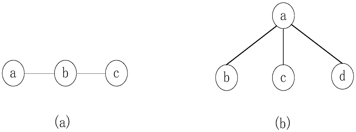
[0058] Example 1: In image 3 In -a, {a,b,c} are three nodes of the network, assuming that nodes a and c are two faulty nodes, and node b is a normal node. Then the detection result of {a,b} is any one of the set {(0,1),(1,1)}, and the result of {b,c} is the set {(1,0),(1, 1)}'s one. When the symptom group is {(0,1),(1,0)}, node b is considered to be in good condition; but when the symptom group is {(1,1),(1,1)}, node b is considered to be failed node, and the remaining combinations are insufficient to determine the status of node b.

example 2

[0059] Example 2: In image 3 In -b, when node a fails, regardless of the state of nodes {b,c,d}, the states of these four nodes are indeterminate.

[0060] Definition 2: The faulty node obtains the correct detection result according to the given probability, and the prior probability p of this probability is defined.

[0061] As a given prior probability p, for faulty node n i , when it detects normal nodes, it gets r with probability p ij = 0 symptom, and get r with probability 1-p ij =1 symptom.

[0062] Given a network, when the network status (e.g., connectivity, time delay, and packet loss rate) is relatively good, the prior probability p is high, and thus dialing test data will be more effective. The detection result is perfectly accurate when p=1, but it only exists in the ideal case.

[0063] 2.2 Dynamic Spanning Tree Search

[0064] In order to detect node faults, combined with the characteristics of high connectivity of the data center network, the present inv...


PUM


Abstract

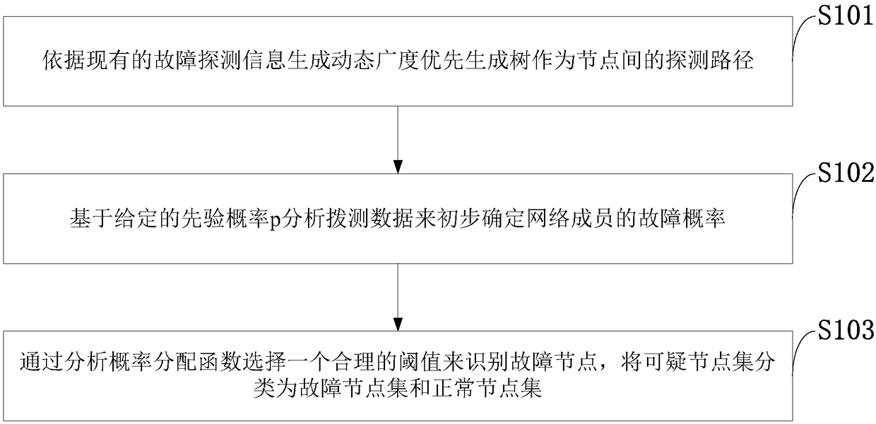
The invention belongs to the technical field of monitoring or testing devices, and discloses a data center network fault node diagnosis method and system based on dialing test data. The method includes the steps of generating a dynamic breadth priority spanning tree as a detection path among nodes on the basis of existing fault detection information, analyzing dialing test data on the basis of a given prior probability p to initially determine the failure probability of network members, selecting a reasonable threshold by analyzing a probability distribution function to identify fault nodes, and classifying a suspicious node set into a fault node set and a normal node set. Compared with an HFD algorithm, an HBFD algorithm has better performance in terms of detection quantity and diagnosticaccuracy. Fault nodes in the network can be accurately identified in network topologies of different sizes in a situation of the low frequency of detection. The introduction of the novel method intoHBFD has a certain research value in order to diagnose malicious nodes or other types of faults in the network.

Description

technical field [0001] The invention belongs to the technical field of supervision, monitoring or testing devices, and in particular relates to a data center network fault node diagnosis method and system based on dial test data. Background technique [0002] At present, the existing technologies commonly used in the industry are as follows: With the advent of the big data era, the increasing demand for cloud computing has led to the continuous expansion of the data center network. Today, data center networks contain hundreds of thousands of servers connected by network interface cards (NICs), switches and routers, cables and fiber optics, most of which are distributed and have high traffic volumes. In large-scale systems, detecting and locating faults is very important for network management systems to restore network communication through fault recovery mechanisms. Although many studies have been devoted to fault diagnosis strategies, there are still issues to be address...

Claims


Application Information

Patent Timeline
Patent Type & Authority Applications(China)
IPC IPC(8): H04L12/24
CPCH04L41/0631H04L41/0636H04L41/0677
Inventor 齐小刚王冰纯刘立芳冯海林胡绍林
Owner XIDIAN UNIV
Learn More