
Fluorine-carbon ratio control method for fluorinated carbon nanotubes

A technology of fluorinated carbon nanotubes and fluorocarbon ratio, which is applied in the direction of fluorinated carbon, can solve the problems of high electronic conductivity and difficult precise control, and achieve the effect of high electronic conductivity

Inactive Publication Date: 2018-12-04
TIANJIN UNIV
View PDF7 Cites 3 Cited by
  • Summary
  • Abstract
  • Description
  • Claims
  • Application Information

AI Technical Summary

Problems solved by technology

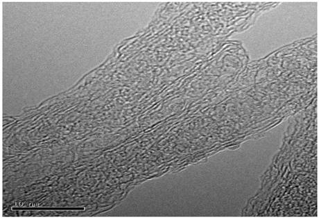
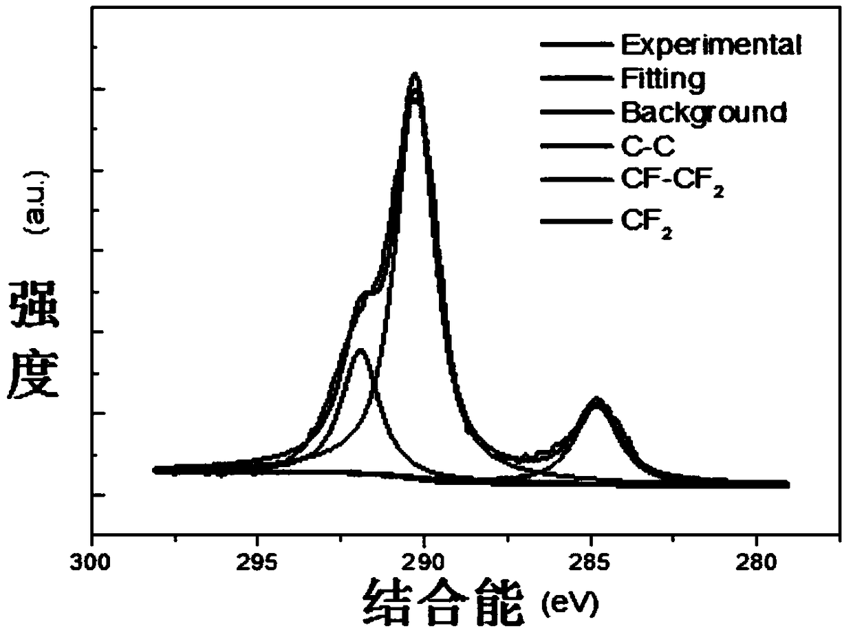
[0004] Aiming at the disadvantage that the fluorinated carbon nanotube process is not easy to accurately control the fluorocarbon ratio, the present invention provides a method for preparing fluorinated carbon nanotubes that are post-treated with a polar solvent to regulate the fluorocarbon ratio. Fluorinated multi-walled carbon nanotubes can control the fluorine-carbon ratio, which can make the carbon tube structure less damaged, maintain high electronic conductivity, and then change the ratio of C-F covalent bonds and ionic bonds, which can be controlled within a wide range. Tuning its structural and electrical properties

Method used


Image

  • Fluorine-carbon ratio control method for fluorinated carbon nanotubes
  • Fluorine-carbon ratio control method for fluorinated carbon nanotubes
  • Fluorine-carbon ratio control method for fluorinated carbon nanotubes

Examples


Embodiment 1

[0020] Mix 60g of fluorinated multi-walled carbon nanotubes and 80mL of isopropanol evenly, sonicate for 1h, then transfer the dispersion to a hydrothermal kettle, raise the temperature to 130°C in a muffle furnace and keep it for 24h; Pour the multi-walled carbon nanotubes into a sand core funnel for suction filtration, wash with deionized water for several times until it is clean, then transfer the filter membrane to a petri dish, place it in a vacuum drying oven, and dry it at 60°C for 24 hours . The fluorine-to-carbon ratio of the fluorinated multi-walled carbon nanotubes was measured to be 0.65.

Embodiment 2

[0022] Mix 80g of fluorinated multi-walled carbon nanotubes and 80mL of tetrahydrofuran evenly, ultrasonicate for 2h, then transfer the dispersion to a hydrothermal kettle, raise the temperature to 150°C in a muffle furnace and keep it for 24h; Wall carbon nanotubes were poured into a sand core funnel for suction filtration, washed with deionized water for several times until clean, then the filter membrane was transferred to a petri dish, placed in a vacuum drying oven, and dried at 60°C for 24 hours. The fluorine-to-carbon ratio of the fluorinated multi-walled carbon nanotubes was measured to be 0.59.

Embodiment 3

[0024] Mix 80g of fluorinated multi-walled carbon nanotubes and 80mL of ethylene glycol evenly, ultrasonicate for 2h, then transfer the dispersion to a hydrothermal kettle, raise the temperature to 150°C in a muffle furnace and keep it for 24h; Pour the multi-walled carbon nanotubes into a sand core funnel for suction filtration, wash with deionized water for several times until it is clean, then transfer the filter membrane to a petri dish, place it in a vacuum drying oven, and dry it at 60°C for 24 hours . The fluorine-to-carbon ratio of the fluorinated multi-walled carbon nanotubes was measured to be 0.76.


PUM


Abstract

The invention discloses a fluorine-carbon ratio control method for fluorinated carbon nanotubes. The method includes warming a mixture to perform reaction after uniformly mixing a fluorinated carbon nanotube and a polar solvent; and using the polar solvent to perform replacement on the fluorine in the carbon nanotube so as to make fluorine atoms detached from the carbon tube, or to weaken the acting force between fluorine and carbon so that defluoridation effects can be achieved. Through the selection of different polar solvents, hydrothermal temperatures and hydrothermal time, the method canwell control the defluorination amount of the carbon tube, and therefore, the fluorine-carbon ratio of the fluorinated carbon nanotube can be controlled; the method is simple in operation and high incontrollability; and compared with high temperature annealing treatments, the method can reduce damages to carbon tube structures and keep the excellent performance of the carbon tubes.

Description

technical field [0001] The invention relates to a method for preparing fluorinated carbon nanotubes with a controllable fluorine-to-carbon ratio. More specifically, a polar solvent is used to defluorinate fluorinated multi-walled carbon nanotubes with high fluorine content to adjust the fluorine-to-carbon ratio. Background technique [0002] With the development of electronic technology, electronic products play an important role in human life, and the performance of batteries directly affects people's experience in use. Therefore, it is particularly critical to develop stable, safe, intelligent and sustainable batteries. Among all energy storage materials, fluorinated carbons have attracted much attention as battery materials due to their high specific energy. Fluorinated carbon nanotubes have higher discharge voltage and rate performance than previously studied fluorinated graphite, and have broad development prospects. However, the fluorocarbon ratio of fluorinated multi...

Claims


Application Information

Patent Timeline
IPC IPC(8): C01B32/10
CPCC01P2002/85C01P2004/03C01P2004/04C01P2004/13C01P2004/133
Inventor 李瑀姚枫楠封伟冯奕钰杨洪宇
Owner TIANJIN UNIV
Learn More