Lower-jaw edentulous jaw implantation assembly, tracker and navigation system and implantation tool

A technology of edentulous jaws and components, which is applied in the fields of dentistry, dental implants, and dental restorations. It can solve the problems of implant surgery failure, implant failure, and prolonging the operation cycle, so as to shorten the implant treatment cycle, improve implant accuracy, and avoid bone loss. burn effect

Active Publication Date: 2018-12-04
SUZHOU DIKAIER MEDICAL TECH
View PDF6 Cites 2 Cited by
  • Summary
  • Abstract
  • Description
  • Claims
  • Application Information

AI Technical Summary

Problems solved by technology

[0006] (1) The guide plate needs to be processed and manufactured by an external technician, and the cycle is longer, which prolongs the operation cycle;
[0007] (2) A plaster model needs to be made during the planting process. The expansion rate of the plaster model itself, the production of the guide plate, and the positioning error will affect the positioning accuracy;
[0008] (3) There are two methods of positioning support for the guide plate: tooth support and mucosal support. For edentulous cases where all the teeth in the jaw are missing, the teeth cannot be used to support the positioning guide plate. Generally, the mucosa is used to support the positioning guide plate. However, , due to the soft nature of the mucosa and the lack of obvious positioning features on the surface of the mucosa, the positioning of the mucosa itself has a certain drift. After the guide plate is in place in the oral cavity, it will shift, sink or warp, which will affect the accuracy of positioning. Moreover, when the patient’s jaw arch is relatively flat, it is difficult to find the exact position of the guide plate, which will affect the accuracy of the guide plate. The accuracy of the operation has a certain impact, and in severe cases, it may even lead to implant failure;
[0010] (5) Once the guide plate is made, the direction of the implant drill cannot be adjusted in time when the operation is performed according to the guide plate. If the fixed point is found to be inaccurate during the operation, it cannot be corrected. The implant socket can only be prepared according to the preoperative design, and the maneuverability is low. At the same time, if the non-flap method is used, there is a risk of damaging important anatomical structures.
[0011] (6) During the operation, it is necessary to cover the guide plate above the implanted area, and then prepare the implanted socket, which will cause the implanted area to be unable to be visualized;
[0012] (7) On the circular abutment of the guide plate, there is usually a metal catheter used to guide the implant drill for drilling during surgery. The position and angle of the catheter record the position, angle and depth of the implant socket designed before the operation. Due to the existence of the catheter, the guide plate is not suitable for the narrow implant area between the two teeth;
[0014] (9) The guide plate is covered above the implant area, and the implant drill needs to enter from the vertical direction of the guide guide guide tube. However, due to the limitation of the patient’s opening (especially the molar area), in actual operation, the implant drill will not be able to enter the guide tube vertically. As a result, the guide plate cannot be used normally during the operation, especially when the opening of the posterior tooth area is not enough, the guide plate can only be discarded, and the implant drill is used to directly drill holes in the jawbone, which cannot ensure the accuracy and safety of the implant. ;
[0015] (10) Due to the use of the guide plate, most of the cooling water flowing from the mobile phone locator is blocked by the guide plate outside the preset implant socket area and cannot flow into the implant socket area for effective cooling. Overheating will lead to irreversible necrosis of the bone cells in this part, which will lead to the failure of implant surgery. Although some guide plates have cooling holes, the amount of cooling water from the mobile phone positioner randomly entering the cooling holes is very small, and the cooling effect is not good. Clinically, there is also a method of injecting cooling water into the cooling hole with a syringe to enhance the cooling effect. However, due to the limited capacity of the syringe, continuous cooling is not possible, and the space occupied by the syringe affects the doctor's operation.

Method used


Image

  • Lower-jaw edentulous jaw implantation assembly, tracker and navigation system and implantation tool
  • Lower-jaw edentulous jaw implantation assembly, tracker and navigation system and implantation tool
  • Lower-jaw edentulous jaw implantation assembly, tracker and navigation system and implantation tool

Examples


Embodiment Construction

[0032] The present invention will be described in detail below in conjunction with specific embodiments shown in the accompanying drawings. However, these embodiments do not limit the present invention, and structural, method, or functional changes made by those skilled in the art according to these embodiments are all included in the protection scope of the present invention.

[0033] In each drawing of the present application, some dimensions of structures or parts are exaggerated relative to other structures or parts for convenience of illustration, and therefore, are only used to illustrate the basic structure of the subject matter of the present application.

[0034] In addition, terms used herein such as "upper", "above", "under", "below", etc. to express relative positions in space are for convenience of description to describe a unit or feature as shown in the drawings relative to A relationship to another cell or feature. The terms of spatial relative position may be...


PUM


Abstract

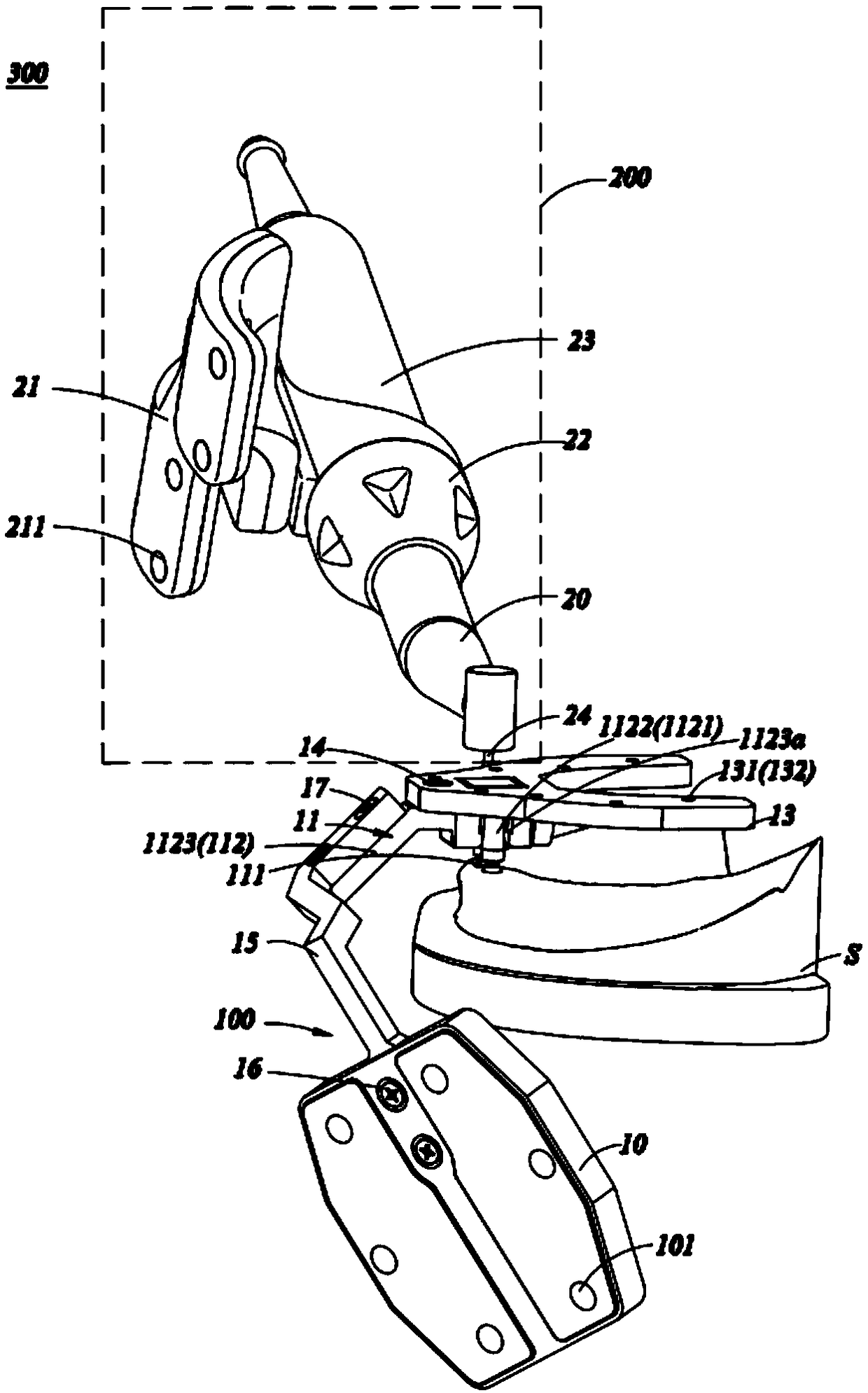
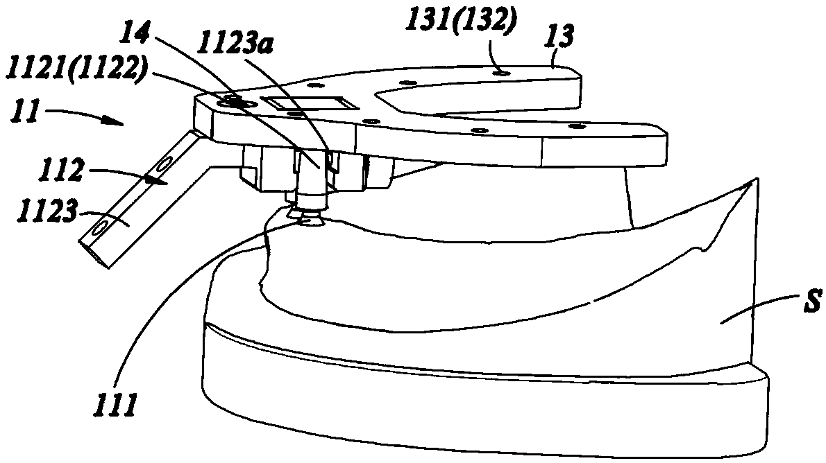
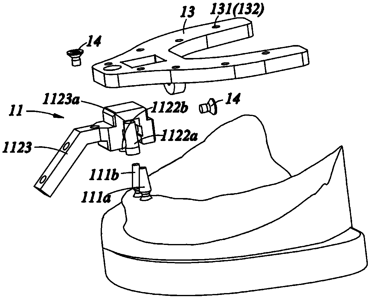
A lower-jaw edentulous jaw implantation assembly, tracker and navigation system and an implantation tool are disclosed. The implantation assembly includes an implant component implanted into a jaw bone and a connection component. The implant component includes adjacent first and second implants. The connection component includes a connection part connected to the implant component and is separatedfrom/cooperates with the implant component through the connection part. The implantation assembly avoids a guide plate arrangement, the adjacent first and second implants are utilized to support theconnection component, and are directly fixed to the jaw bone and an occupied implantation space is extremely small. Beneficial effects are that (1) the implantation precision is greatly improved and apreoperative digitally designed position can be achieved precisely; (2) an implantation zone is completely opened, facilitating flowing of cooling water into implantation holes; (3) an implantation scheme can be adjusted during an operation; (4) an original implantation drill is used and is suitable for parts with poor mouth opening degrees in backteeth zones and narrow implantation zones; and (5) the implantation treatment period is shortened.

Description

technical field [0001] The invention relates to the field of medical devices, in particular to a mandibular edentulous implant assembly, a tracker, a navigation system and an implant tool. Background technique [0002] The traditional dental implant surgery is to take a panoramic film of the patient before the operation. The doctor can roughly judge whether the patient's tooth loss can be repaired by implantation by observing the panoramic film, and roughly determine the diameter of the implant and the bone mass displayed on the panoramic film. length. [0003] However, due to the inability of panoramic films to accurately provide the patient's bone information and the limitation of doctors' clinical experience, doctors often need to measure on-site during the operation, but this is limited to the mesial-distal length of the jaw in the edentulous area and the bone The width of the bone cannot be measured, and the doctor’s blind operation is prone to errors, resulting in ner...

Claims


Application Information

Patent Timeline
Patent Type & Authority Applications(China)
IPC IPC(8): A61C8/00
CPCA61C8/00A61C8/0089A61C2201/005
Inventor 满毅杨醒眉郁峰罗哲
Owner SUZHOU DIKAIER MEDICAL TECH
Why Eureka
Try Eureka