Modeling grid structure thermal insulation wall and construction method

A technology for thermal insulation of walls and grids, which is applied in the direction of thermal insulation, walls, and building components. It can solve the problems that composite thermal insulation free formwork cannot be produced according to drawings, the production process of sandwich thermal insulation technology is cumbersome, and the quality of the project cannot be guaranteed. , to achieve the effect of excellent structural quality, good thermal insulation effect and low operability

Pending Publication Date: 2018-11-30
陈红庆
View PDF5 Cites 5 Cited by
  • Summary
  • Abstract
  • Description
  • Claims
  • Application Information

AI Technical Summary

Problems solved by technology

The disadvantage of this technology is that it is generally cracked and easy to fall off. If B-grade materials are used, it will not meet the fire protection requirements of the 2015 Building Design Fire Protection Code. Even if A-grade materials are used, the life span of the main body will not be reached.
Second, the production process of the existing sandwich insulation technology is cumbersome, the construction requires self-compacting concrete, the construction is difficult, and the quality of the project cannot be guaranteed
Its three-composite thermal insulation free formwork technology mainly cannot be produced according to the drawings, and the joints will freeze and thaw after being soaked in water, deform, crack, and fall off

Method used


Image

  • Modeling grid structure thermal insulation wall and construction method
  • Modeling grid structure thermal insulation wall and construction method
  • Modeling grid structure thermal insulation wall and construction method

Examples


Embodiment Construction

[0025] The following will clearly and completely describe the technical solutions in the embodiments of the present invention with reference to the accompanying drawings in the embodiments of the present invention. Obviously, the described embodiments are only some, not all, embodiments of the present invention. Based on the embodiments of the present invention, all other embodiments obtained by persons of ordinary skill in the art without making creative efforts belong to the protection scope of the present invention.

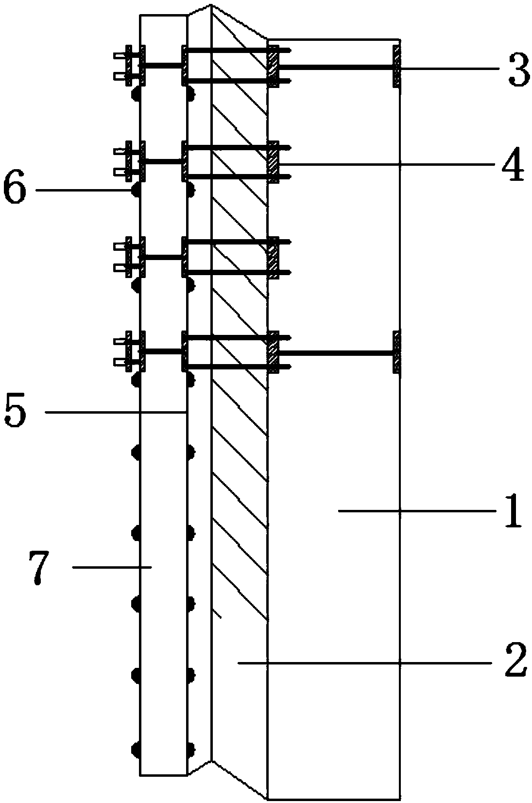
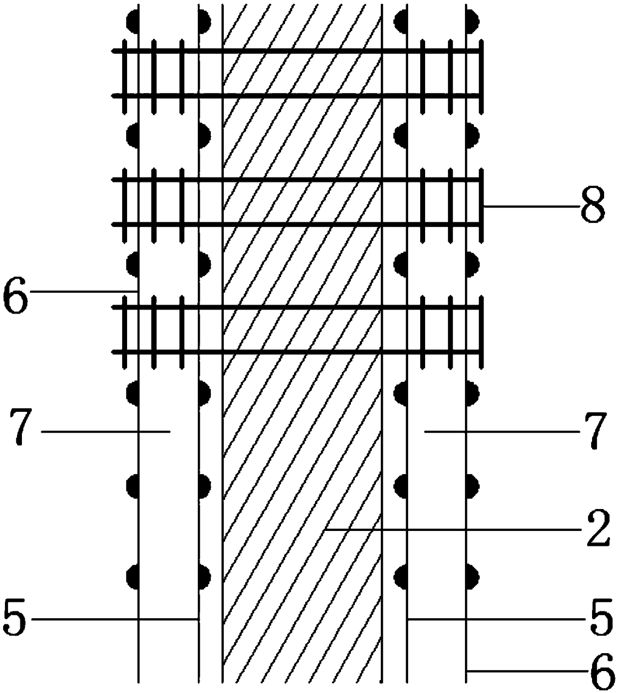
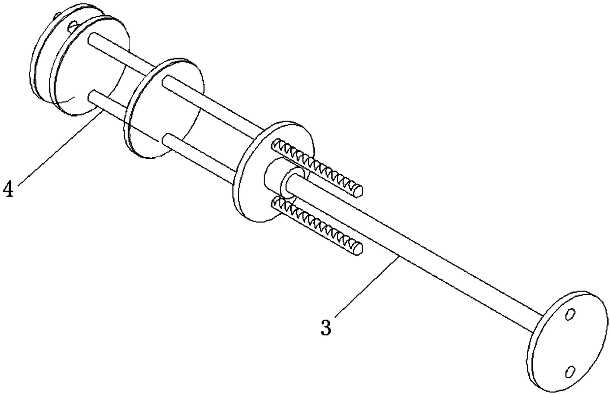
[0026] see Figure 1~4 , In an embodiment of the present invention, a plastic grid frame insulation wall includes a shear wall (load-bearing wall) and a filling wall.

[0027] The shear wall (load-bearing wall), including the reinforced concrete wall of the shear wall (load-bearing wall), the thermal insulation layer outside the shear wall (load-bearing wall), and the first fixing on the outside of the thermal insulation layer Steel wire mesh, the second anti...


PUM


Abstract

The invention discloses a modeling grid structure thermal insulation wall and a construction method. The modeling grid structure thermal insulation wall comprises a shear wall and a filler wall, wherein a thermal insulation board is arranged on an outer layer of the shear wall; two layers of steel wire meshes are arranged on the outer side of the thermal insulation board of the shear wall, and twolayers of steel wire meshes are arranged on the inner side and the outer side of a thermal insulation board of the filler wall; the steel wire meshes comprise fixed steel wire meshes and anti-crack steel wire meshes, the fixed steel wire meshes are arranged outside the thermal insulation boards, the anti-crack steel wire meshes are arranged on outer layers of the fixed steel wire meshes, and thefixed steel wire meshes and the anti-crack steel wire meshes are connected by adopting mesh-frame-type connecting pieces; supporting pieces are installed at the inner side ends of the mesh-frame-typeconnecting pieces, and the supporting pieces are arranged on the mesh-frame-type connecting pieces in a penetrating mode; and the supporting pieces are connected to the inner sides of the mesh-frame-type connecting pieces through screw threads or clamping grooves in a fastening mode. The modeling grid structure thermal insulation wall and the construction method have a simple production process, agood thermal insulation effect, good fireproof performance, no falling off, fast construction progress and capability of maintaining the same technological life as a building.

Description

technical field [0001] The invention relates to the technical field of construction methods for thermal insulation walls of building exterior walls, in particular to a thermal insulation wall with plastic grid frames and a construction method. Background technique [0002] Existing external wall thermal insulation is mainly external adhesive technology, sandwich thermal insulation technology and composite thermal insulation free formwork technology. One is the traditional thermal insulation technology, which is to stick the thermal insulation material to the outer wall of the building with adhesive mortar. Then fix it on the wall with insulation nails, and do a thin plastering treatment on the surface. The disadvantage of this technology is that it is generally cracked and easy to fall off. If B-grade materials are used, it will not meet the fire protection requirements of the 2015 Building Design Fire Protection Code, and even if A-grade materials are used, the life span of...

Claims


Application Information

Patent Timeline
Patent Type & Authority Applications(China)
IPC IPC(8): E04B2/84E04B1/80
CPCE04B1/80E04B2/842E04B2/845E04B2/847
Inventor 陈红庆
Owner 陈红庆
Why Eureka
Try Eureka