Temperature-adjusting electric kettle
A technology for electric kettles and temperature adjustment, which is applied to heating devices, cooking utensils, and water boiling utensils, etc., which can solve the problems of inability to keep heat, cannot be quickly cooled, etc., and achieve the effects of saving time, saving electric energy, and obvious technical and economic benefits
- Summary
- Abstract
- Description
- Claims
- Application Information
AI Technical Summary
Problems solved by technology
Method used
Image
Examples
Embodiment 1
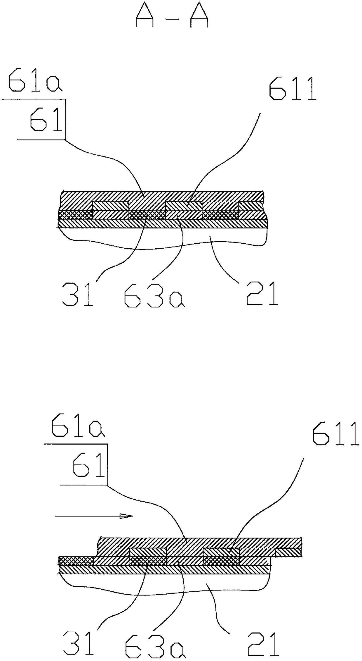
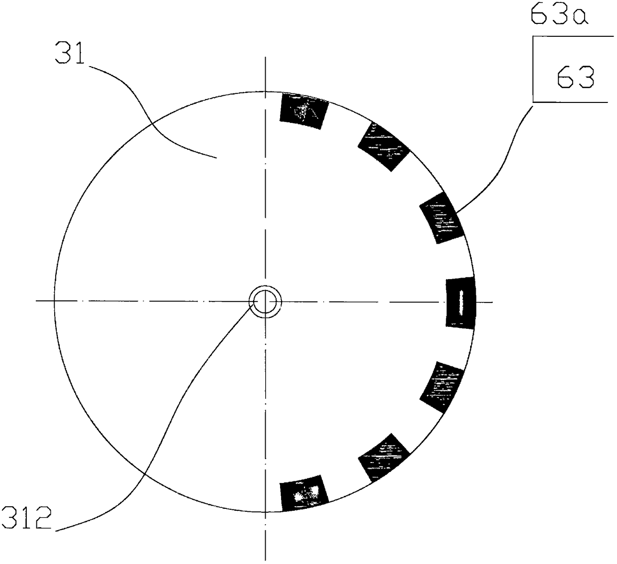
[0040] This example is a thermostat electric kettle, such as figure 1 , 2 , 3 and 4, including base 10, kettle body 20 placed on the base, kettle lid 30, electric heating plate 40 placed in the kettle body, electric control device 50 and heat dissipation device 60 placed in the kettle lid. The kettle body is movably placed on the base, the kettle body bottom is provided with a power connector 21, and the base is provided with a power socket 11, the power connector 21 and the power socket 11 can adopt the prior art, when the kettle body is placed on the base, the power connector 21 can be easily inserted in the power socket 11 on the base, and connect the power supply in the kettle body. The wall of the kettle body 20 is a sandwich structure, and the interlayer is evacuated; the bottom plate 31 of the kettle cover 30 is made of heat-insulating material, and the opening of the kettle body is fully covered during work; the electric control device 50 includes a control circuit boar...
Embodiment 2
[0054] Another kind of kettle lid 30 cut-away enlarged schematic diagram of this example temperature-regulating electric kettle is as Figure 5 As shown, this example is basically similar to Example 1, the difference lies in:
[0055] The radiating fins 61 are movable fins 61b, the edge of which is provided with a heat conduction lip 61b1, and the movable fins 61b are movably installed in the lid 30, and can be driven by a driving device 64 to move along the guide rail 66 to make the heat conduction lip 61b1 is inserted into or extracted from the gap between the upper end of the kettle body 20 and the lower edge of the kettle cover 30 to realize communication or cut off the heat conduction between the movable fin 61b and the inner wall of the kettle body 20 . When the heat-conducting lip 61b1 is inserted into the gap between the upper end of the kettle body 20 and the lower edge of the kettle cover 30, it will be in close contact with the upper end of the kettle body 20. Becau...
Embodiment 3
[0057] This example Figure 6 , 7 As shown, basically similar to example two, the cooling fin 61 of this example is also a movable fin 61b, which is movably installed in the pot lid 30 and can move along the guide rail 66; the difference with example two mainly lies in:
[0058] The heat-conducting element 63 is a cylindrical panel 63b, which is cylindrical and fixed in the pot body 20. The middle and lower parts are immersed in the water in the pot, and the upper part extends into the pot lid, and the movable fin 61b is driven by the driving device 64. Move, make its edge and column plate 63b contact each other or separate from each other, their contact surfaces have the shape that fits each other, fin and column plate 63b are made of good thermal conductivity material such as aluminum alloy, copper alloy. The end portion of the movable fin 61b is fixed with an insulating cover 67 for preventing heat radiation. In the heat preservation state, the edge of the movable fin 61b ...
PUM
 Abstract
Description
Claims
Application Information
 - Generate Ideas
- Intellectual Property
- Life Sciences
- Materials
- Tech Scout
- Unparalleled Data Quality
- Higher Quality Content
- 60% Fewer Hallucinations
Browse by: Latest US Patents, China's latest patents, Technical Efficacy Thesaurus, Application Domain, Technology Topic, Popular Technical Reports.
© 2025 PatSnap. All rights reserved.Legal|Privacy policy|Modern Slavery Act Transparency Statement|Sitemap|About US| Contact US: help@patsnap.com


