Large-span gas film ultralow-temperature environment heat insulation device

A thermal insulation device and ultra-low temperature technology, applied in thermal insulation, building components, arched structures, etc., can solve problems such as difficult to meet thermal insulation requirements, easy to form cold bridge phenomenon, poor thermal insulation effect, etc., to achieve good thermal insulation effect, Reduced energy consumption and operating costs, and long service life

Inactive Publication Date: 2021-07-23
SHENZHEN ZHONGDE MEMBRANE STRUCTURE CO LTD
View PDF6 Cites 0 Cited by
  • Summary
  • Abstract
  • Description
  • Claims
  • Application Information

AI Technical Summary

Problems solved by technology

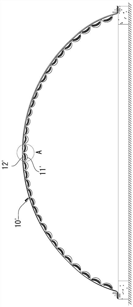
[0004] refer to Figure 1 to Figure 2 As shown, a kind of air film insulation structure is disclosed in the related art, in which a number of air pillows 11' are arranged on the inner wall of the air film 10', and thermal insulation materials 12' are filled in the air pillows 11'. The position between the adjacent two air pillows 11' cannot be covered by the thermal insulation material 12', therefore, between the two adjacent air pillows 11', due to the temperature difference between the inside and outside of the air film 10', it is easy to form cold Bridge phenomenon, and cold bridge phenomenon is an important factor for high energy consumption
In addition, when filling the thermal insulation material 12', it is necessary to penetrate the sheet-shaped thermal insulation material 12' into the air pillow 11' when the air pillow 11' is inflated. Due to the difficulty of construction, the thermal insulation material 12' is usually not fully filled. The air pillow 11' has no positions filled with thermal insulation material 12' on both sides, which will also cause increased power consumption, and the thermal insulation effect is poor, so it is difficult to meet the thermal insulation requirements in ultra-low temperature environments

Method used


Image

  • Large-span gas film ultralow-temperature environment heat insulation device
  • Large-span gas film ultralow-temperature environment heat insulation device
  • Large-span gas film ultralow-temperature environment heat insulation device

Examples


Embodiment Construction

[0062] Embodiments of the present invention are described in detail below, examples of which are shown in the drawings, wherein the same or similar reference numerals designate the same or similar elements or elements having the same or similar functions throughout. The embodiments described below by referring to the accompanying drawings are exemplary and are intended to explain the present invention, but cannot be construed as limitations to the present invention. Based on the embodiments in the present invention, those skilled in the art do not make creative work premise All other embodiments obtained below all belong to the protection scope of the present invention.

[0063] In describing the present invention, it should be understood that the terms "center", "longitudinal", "transverse", "length", "width", "thickness", "upper", "lower", "front", " Back", "Left", "Right", "Vertical", "Horizontal", "Top", "Bottom", "Inner", "Outer", "Clockwise", "Counterclockwise", "Axial",...


PUM

PropertyMeasurementUnit
thermal conductivityaaaaaaaaaa

Abstract

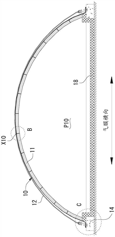
The invention discloses a large-span gas film ultralow-temperature environment heat insulation device. The large-span gas film ultralow-temperature environment heat insulation device comprises a gas film and a heat insulation pasting material layer, wherein the edge of the gas film is sealed on a base body to define a building space; the heat insulation material pasting layer is located in the building space, and the heat insulation material pasting layer is pasted on the inner wall of the gas film through an adhesive. The large-span gas film ultralow-temperature environment heat insulation device is good in heat insulation and heat preservation effect and is particularly suitable for ultralow-temperature environments such as refrigeration houses and ski fields, the requirement for the heat insulation and heat preservation effect in the environments is met, and the energy consumption and the operation cost are reduced; in addition, the service life is long, and the structure is simple.

Description

technical field [0001] The invention relates to air-film buildings, in particular to a large-span air-film ultra-low temperature environment heat insulation device. Background technique [0002] Air film building refers to a building structure system that uses special architectural membrane materials as the shell and is equipped with a set of intelligent electromechanical equipment to provide positive air pressure inside the air film building and support the main body of the building. [0003] Air film buildings are mostly used in sports venues, warehouses, industrial plants, cold storage, ski resorts and other scenarios. Among them, when used in ultra-low temperature environments such as cold storage and ski resorts, the thermal insulation performance of the air film is high, such as the temperature of the cold storage It needs to be maintained at -18°C or lower, and the temperature of the ski resort needs to be maintained at around -5°C. In these ultra-low temperature envi...

Claims


Application Information

Patent Timeline
Patent Type & Authority Applications(China)
IPC IPC(8): E04B1/34E04B1/32E04B1/76E04B1/78
CPCE04B1/34E04B1/3211E04B1/762E04B1/7625E04B1/78
Inventor 周茂亦汪妍君劳歆淇
Owner SHENZHEN ZHONGDE MEMBRANE STRUCTURE CO LTD
Why Eureka
Try Eureka