
Motor rotor, assembly method thereof and motor

A motor rotor and rotor core technology, applied in the direction of electromechanical devices, electrical components, electric components, etc., can solve the problems of irreversible demagnetization of magnetic steel, poor structural integrity, heat generation, etc., to improve connection reliability, position stability, The effect of preventing mechanical damage

Active Publication Date: 2018-11-23
GREE ELECTRIC APPLIANCES INC +1
View PDF6 Cites 4 Cited by
  • Summary
  • Abstract
  • Description
  • Claims
  • Application Information

AI Technical Summary

Problems solved by technology

[0003] However, since the existing slot wedge 3' is mostly made of non-metallic insulating material, and the end ring 4' is made of metal non-magnetic material, the two cannot be connected together structurally, the stability and reliability of the rotor connection is not high, and the structural integrity is poor; In addition, when the load of the motor is unbalanced or the motor has an asymmetrical short circuit, the rotor will have a short-term axial flow current. The frequency of this current is the induced current twice the frequency of the inverter current. The induced current will heat the rotor, which is extremely dangerous. It may cause irreversible demagnetization of the magnetic steel, that is, the existing slot wedge structure cannot protect the rotor under abnormal conditions of motor operation

Method used


Image

  • Motor rotor, assembly method thereof and motor
  • Motor rotor, assembly method thereof and motor
  • Motor rotor, assembly method thereof and motor

Examples


Embodiment Construction

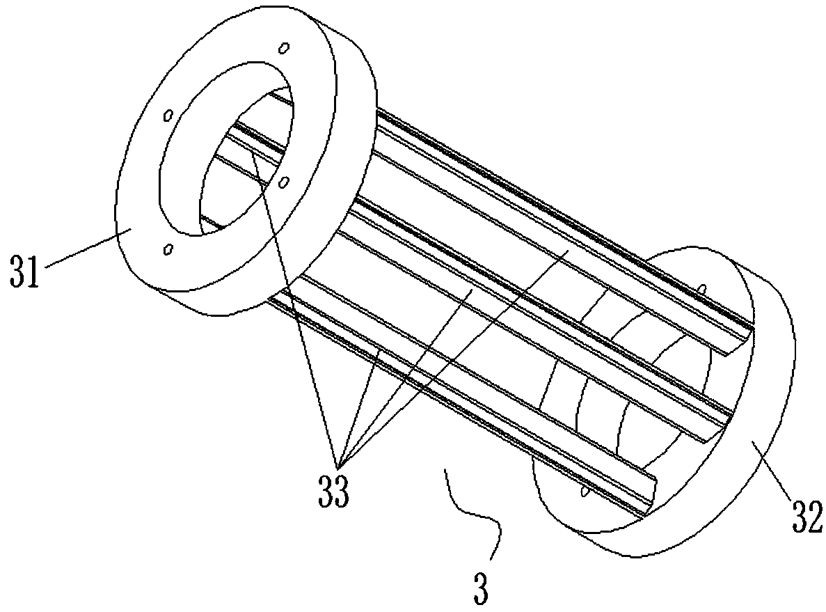
[0024] see in conjunction Figures 1 to 4 As shown, according to an embodiment of the present invention, a motor rotor is provided, which is used in a permanent magnet synchronous motor, including a rotor core 2, and the two ends of the rotor core 2 are respectively provided with a first end ring 31, a second The end ring 32, a plurality of magnetic isolation guide bars 33 are connected between the first end ring 31 and the second end ring 32, and the plurality of magnetic isolation guide bars 33 pass through the rotor core 2. In the groove 21 , the rotor core 2 has a plurality of magnetic steel slots 23 , and the groove 21 is located in a region between two adjacent magnetic steel slots 23 with opposite magnetic poles. In this technical solution, the groove 21 is arranged in the area between the adjacent magnetic steel grooves 23 with opposite polarities, and the magnetic isolation guide bar 33 is passed through the groove 21, so that there is no need to use existing There i...


PUM


Abstract

The invention provides a motor rotor, an assembly method and a motor. The motor rotor is used in a permanent-magnet synchronous motor and comprises a rotor core, wherein a first end ring and a secondend ring are respectively arranged at two ends of the rotor core, a plurality of magnetic isolation guide strips are connected between the first end ring and the second end ring, the plurality of magnetic isolation guide strips penetrate through grooves in the rotor core, a plurality of magnetic steel grooves are formed in the rotor core, and the grooves are arranged in a region between two magnetic steel grooves with opposite-polarity magnetic poles. In the motor rotor, the assembly method thereof and the motor, provided by the invention, the magnetic isolation guide strips are connected withthe end rings, the connection reliability and the structure integration of the motor rotor are improved, and meanwhile, magnetic isolation can be performed on adjacent opposite-polarity magnetic poles of the motor rotor.

Description

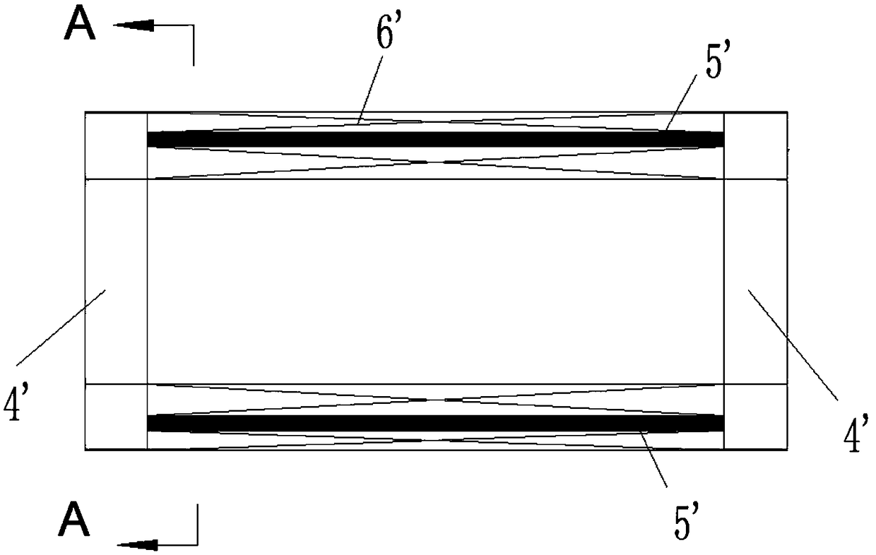
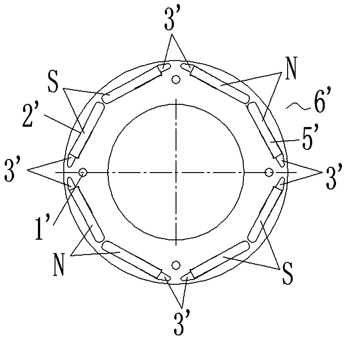
technical field [0001] The invention belongs to the technical field of motor manufacturing, and in particular relates to a motor rotor, an assembly method thereof, and a motor. Background technique [0002] At present, high-speed permanent magnet synchronous motors are developing rapidly and are widely used in centrifuges and other working conditions of HVAC equipment. Due to the high speed of the motor (generally above 10,000rpm) and the large moment of inertia of the rotor, the rotor structure generally adopts the impact motor. Slender rotor core with small outer diameter and large stack thickness (embedded magnetic steel 5'), figure 1 A side view of the current motor rotor is given, figure 2 gives figure 1 The sectional view of the motor rotor of the structure shows the common structure of the current high-speed permanent magnet synchronous motor rotor punching plate 6', in which four small round holes 1' can be used for cooling and ventilation, and eight long slots 2'...

Claims


Application Information

Patent Timeline
Patent Type & Authority Applications(China)
IPC IPC(8): H02K1/27
CPCH02K1/276
Inventor 黄积光王周叶周成海龚敏龙胜民伍尚权贾金信
Owner GREE ELECTRIC APPLIANCES INC
Learn More