Efficient heat dissipation device of automatic power cabinet

A technology for heat dissipation device and power cabinet, which is applied in the cooling/ventilation of substation/switchgear, substation/switch layout details, electrical components, etc. Affecting issues such as safe electricity use, to achieve the effect of lowering temperature, good heat dissipation effect, and efficient heat conduction efficiency

Inactive Publication Date: 2018-11-23
太仓市友达电气技术有限公司
View PDF5 Cites 1 Cited by
  • Summary
  • Abstract
  • Description
  • Claims
  • Application Information

AI Technical Summary

Problems solved by technology

The existing power cabinets are used outdoors. Due to the influence of outdoor factors, dust will enter the heat dissipation windows. After a long time, the heat dissipation windows will be sealed by dust, which makes the heat of the power cabinets affect the safe use of electricity and speeds up the internal heat dissipation of the power cabinets. The service life of the equipment increases the cost of use, and the heat dissipation effect of the power equipment is poor. Generally, the power equipment will be equipped with heat dissipation ribs, but the heat of the heat dissipation ribs cannot be dissipated in the power cabinet, and it is easy to cause failure. Therefore, we propose a High-efficiency heat dissipation device for automatic power cabinet

Method used


Image

  • Efficient heat dissipation device of automatic power cabinet
  • Efficient heat dissipation device of automatic power cabinet
  • Efficient heat dissipation device of automatic power cabinet

Examples


Embodiment Construction

[0017] The following will clearly and completely describe the technical solutions in the embodiments of the present invention with reference to the accompanying drawings in the embodiments of the present invention. Obviously, the described embodiments are only some, not all, embodiments of the present invention.

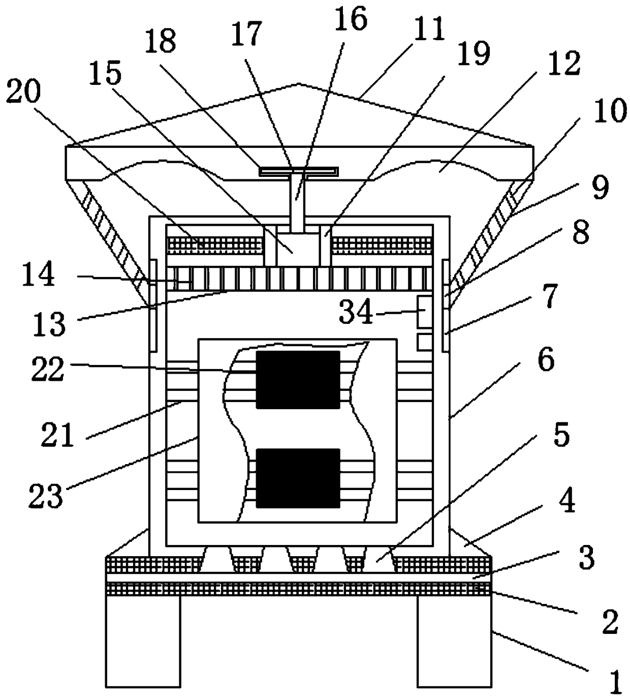
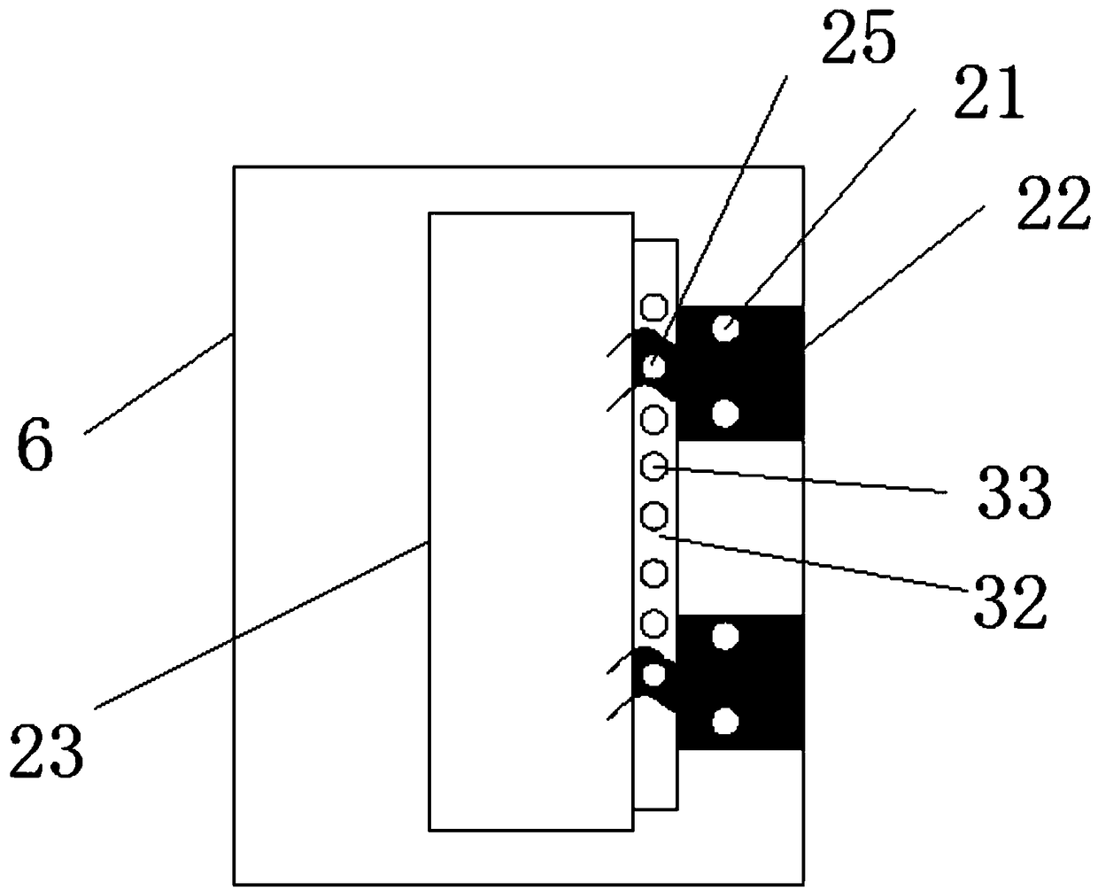
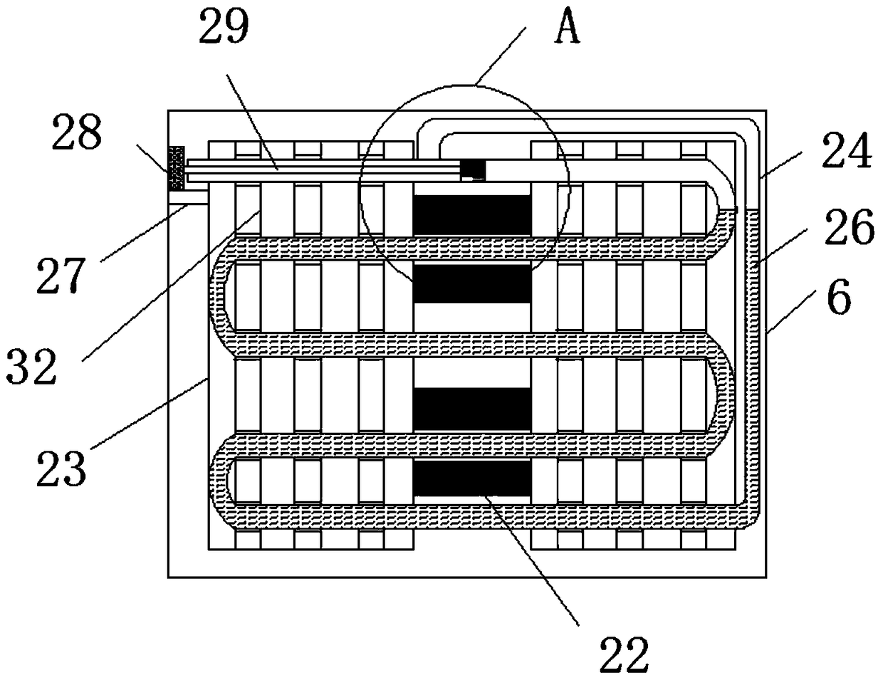
[0018] refer to Figure 1-4 , a high-efficiency heat dissipation device for an automated power cabinet, comprising a cabinet body 6, a temperature sensor 34 and a PLC controller are installed on the upper side of the inner wall of the cabinet body 6, a triangular plate 4 is arranged on the outer lower part of the cabinet body 6, and the lower end of the cabinet body 6 The first through holes 5 are equidistantly opened, and the middle part of the bottom plate 2 is provided with a heat dissipation hole 3 communicating with the first through hole 5, which can improve the heat dissipation efficiency of the cabinet body 6, so that the internal temperature can be maintained...


PUM


Abstract

The invention relates to the technical field of power cabinets, in particular to an efficient heat dissipation device of an automatic power cabinet. The efficient heat dissipation device comprises a cabinet body, wherein transverse plates are arranged at the upper part of an inner cavity of the cabinet body; air inlets are uniformly formed in the surfaces of the transverse plates; a first air cylinder is arranged between fixed plates; the upper end of the first air cylinder is connected with a first push plate through the first air cylinder via a first supporting rod; one end, far away from the first supporting rod, of the first push plate is connected with a cover body; heat conduction pieces are arranged on one side, close to a mounting block, of each power cabinet control panel at equalintervals; second through holes are formed in the outer sides of the plurality of heat conduction pieces at equal intervals; inserting holes corresponding to the second through holes are formed in each mounting block; and the fixed plates are arranged on the upper parts of the outer sides of the power cabinet control panels. Compared with the prior art, the efficient heat dissipation device has the advantages of being high in advantages, better in heat dissipation effect and more automatic, so that the service life of equipment is prolonged consequently, the cost is lowered, faults are avoided, and the device is very practical and worthy of later popularization and use.

Description

technical field [0001] The invention relates to the technical field of power cabinets, in particular to an efficient heat dissipation device for an automated power cabinet. Background technique [0002] The power cabinet is a commonly used power infrastructure. It is equipped with a large number of power components. When the power cabinet is working, it will generate a lot of heat inside. It can be used as a power meter and hung on the power grid separately. At the same time, it can save wiring and reduce space. . The existing power cabinets are used outdoors. Due to the influence of outdoor factors, dust will enter the heat dissipation windows. After a long time, the heat dissipation windows will be sealed by dust, which makes the heat of the power cabinets affect the safe use of electricity and speeds up the internal heat dissipation of the power cabinets. The service life of the equipment increases the cost of use, and the heat dissipation effect of the power equipment i...

Claims


Application Information

Patent Timeline
Patent Type & Authority Applications(China)
IPC IPC(8): H02B1/56G05D23/27
CPCG05D23/27H02B1/565
Inventor 卢启明
Owner 太仓市友达电气技术有限公司
Why Eureka
Try Eureka