Method for incinerating petrochemical industry waste liquid based on mixed fuel of gas and oily liquid

A petrochemical, liquid mixing technology, applied in combustion methods, combined combustion mitigation, incinerators, etc., can solve the problems of petrochemical waste alkali environmental pollution, unreasonable use ratio, high processing cost, and avoid exhaust pollution and even flameout. Parking problem, cost reduction effect is outstanding, the effect of reducing processing cost

Active Publication Date: 2018-11-23
CHINA PETROLEUM & CHEM CORP +1
View PDF8 Cites 2 Cited by
  • Summary
  • Abstract
  • Description
  • Claims
  • Application Information

AI Technical Summary

Problems solved by technology

[0005] In view of the defects existing in the prior art, the purpose of the present invention is to provide a device that realizes a reasonable combustion load by adjusting gaseous fuel, liquid fuel and petrochemical waste liquid to a reasonable ratio, reduces treatment costs, and reduces the impact of excessive combustion load on the device. The method of incinerating waste liquid of petrochemical industry, which overcomes the technical defect of unreasonable ratio of gas and liquid fuel, broadens the adaptability of fuel, and solves the problem of environmental pollution and high processing cost of petrochemical waste alkali in the prior art question

Method used


Image

  • Method for incinerating petrochemical industry waste liquid based on mixed fuel of gas and oily liquid
  • Method for incinerating petrochemical industry waste liquid based on mixed fuel of gas and oily liquid
  • Method for incinerating petrochemical industry waste liquid based on mixed fuel of gas and oily liquid

Examples


Embodiment Construction

[0023] The implementation of the present invention will be described in detail below in conjunction with the examples. If specific conditions are not indicated in the examples, it shall be carried out in accordance with conventional conditions or common conditions in the same industry.

[0024] A 100,000-ton level cyclohexanone spent caustic soda incineration plant, including water-cooled walls, water-cooled panels, evaporation tube panels, steam drums, economizers, and air preheaters, etc. The water-cooled walls form a square combustion chamber with a size of 3.85m× 3.85 meters, the waste liquid incineration treatment process method is:

[0025] After the saponification waste lye is pressurized to 1.8-2.5MPa, it is sent to the saponification liquid spray gun, and enters the alkali recovery boiler after atomization, where it is suspended and dried in the furnace and burned in space (suspension combustion). The organic sodium salt in the saponification solution is converted into Na ...
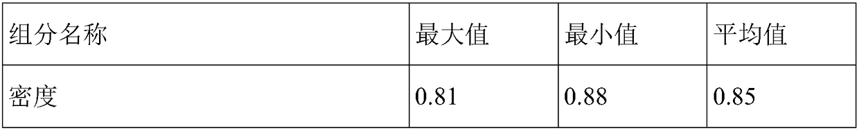

PUM


Abstract

The invention discloses a method for incinerating petrochemical industry waste liquid based on mixed fuel of gas and oily liquid. The method comprises the steps of spraying the petrochemical industrywaste liquid into a combustion area of a spent caustic incinerator in an atomized manner, using fuel gas and oily liquid as combustion-supporting fuel, and carrying out combustion on the condition ofblowing in gas with oxygen while controlling the temperature of the combustion area to range from 800 DEG C to 1, 200 DEG C, wherein the material input of petrochemical industry waste liquid, and thematerial input of the fuel gas and the oily liquid simultaneously meet the requirements that the ratio of petrochemical industry waste liquid quantity per hour to spent caustic incinerator combustionarea hearth cross sectional area ranges from 0.7 to 1.0 t / h.m2, the ratio of fuel gas quantity per hour to spent caustic incinerator combustion area hearth cross sectional area ranges from 0.05 to 0.09 t / h.m2, and the ratio of oily liquid quantity per hour to spent caustic incinerator combustion area hearth cross sectional area ranges from 0.03 to 0.08 t / h.m2. With the method for incinerating petrochemical industry waste liquid based on mixed fuel of gas and oily liquid, it can be achieved that the combustion load is reasonable, the processing cost is reduced, damage caused by overhigh combustion load to a device is reduced, and it is beneficial for a waste liquid incineration technology to be promoted and applied to industries.

Description

Technical field [0001] The invention relates to a method for processing petrochemical waste liquid, more specifically to a method for simultaneously using combustible gas and oily fuel to incinerate petrochemical waste liquid, belonging to the technical field of petrochemical industry. Background technique [0002] The petrochemical industry, such as the industrial process of cyclohexane oxidation to produce cyclohexanone, produces a large amount of high-concentration organic waste lye, and its treatment to meet the standard was once an environmental bottleneck for the expansion of the industry. In the late 1990s, Sinopec Baling Company successfully developed a waste alkali incineration technology based on the alkali recovery furnace method, which has the advantages of high COD removal rate and compliance with national environmental emission standards after treatment. It has gradually become a cyclohexanone saponification waste alkali treatment The mainstream technology has been ...

Claims


Application Information

Patent Timeline
IPC IPC(8): F23G7/04
CPCF23G7/04F23G2204/103F23G2206/203F23G2209/101Y02E20/12
Inventor 黎树根陈立新张君辉李勇军
Owner CHINA PETROLEUM & CHEM CORP
Why Eureka
Try Eureka