
Metal oxyfluoride films for chamber components

A fluoride and oxide coating technology, used in metal layered products, metal material coating processes, electrical components, etc., can solve problems such as process drift and etching rate decline

Inactive Publication Date: 2018-11-23
APPLIED MATERIALS INC
View PDF10 Cites 7 Cited by
  • Summary
  • Abstract
  • Description
  • Claims
  • Application Information

AI Technical Summary

Problems solved by technology

However, the YF 3 Coatings applied to chamber components of etch reactors have been shown to cause significant etch rate drops (e.g., up to 60% etch rate drops), process drift, and chamber matching issues

Method used


Image

  • Metal oxyfluoride films for chamber components
  • Metal oxyfluoride films for chamber components
  • Metal oxyfluoride films for chamber components

Examples


Embodiment Construction

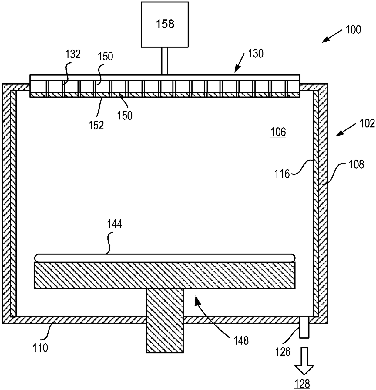
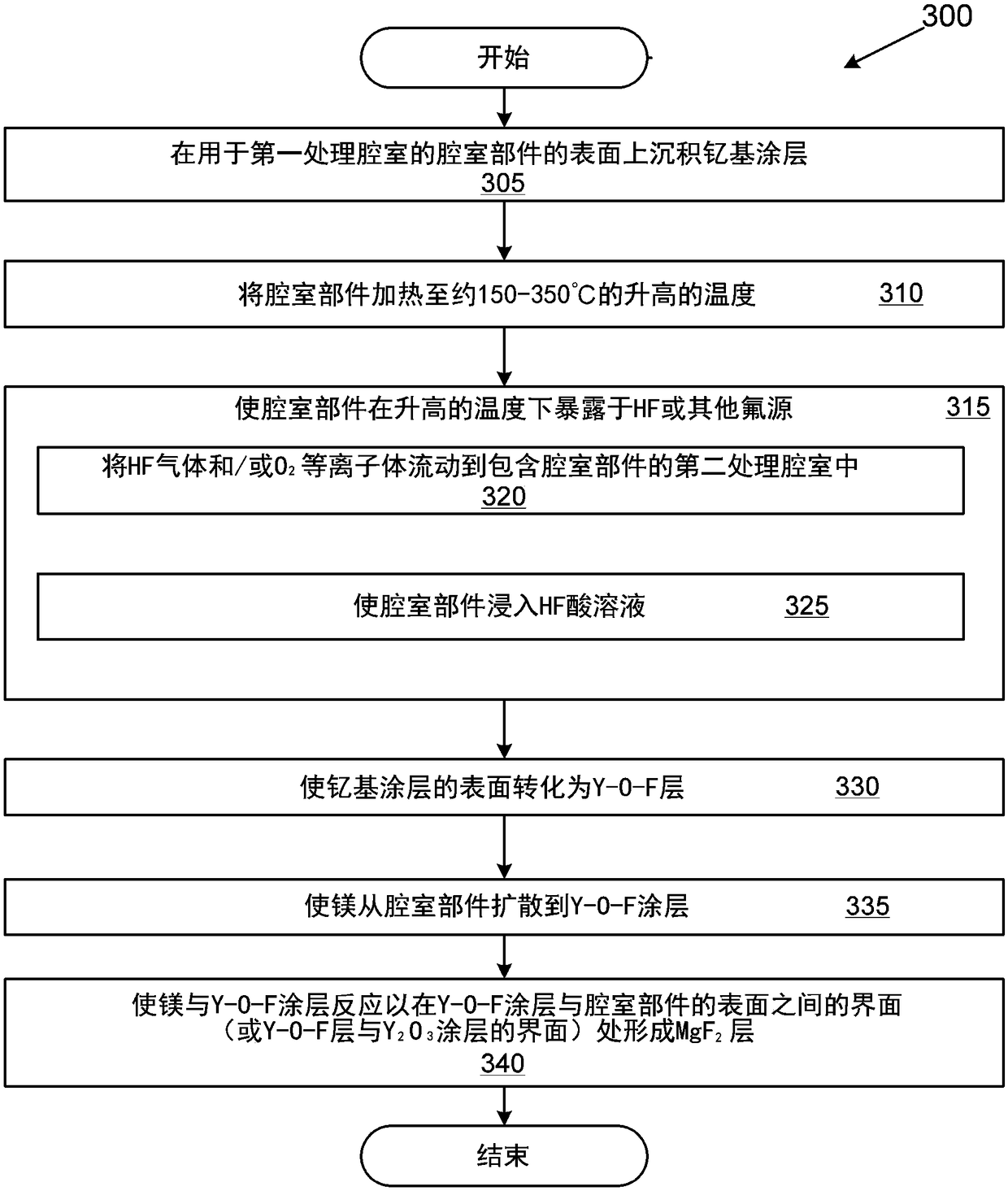
[0039] Embodiments of the invention are directed to processes for forming Y-O-F layers and coatings and other M-O-F layers and coatings, where M is a metal, such as Al, a rare earth metal, or a combination of metals. Y-O-F coatings and layers and other yttrium oxyfluoride coatings and layers are highly resistant to attack and corrosion by fluorine-based plasmas. Additionally, M-O-F coatings are generally resistant to fluorination by fluorine-based plasmas. In addition, M-O-F coatings can resist M(OH) (such as, Y(OH) 3 )Formation. In addition, M-O-F coating does not cause when using YF 3 The etch rate observed decreases when coating chamber components. Given these characteristics, Y-O-F and other M-O-F coatings and layers as described herein provide significant particle reduction and also improve etch rate uniformity and chamber-to-chamber uniformity when used on chamber components for processing chambers . In the embodiments, the term "M-O-F" means 1-99 atomic % of M, 1-9...


PUM

PropertyMeasurementUnit
thicknessaaaaaaaaaa
thicknessaaaaaaaaaa
thicknessaaaaaaaaaa

Abstract

An article comprises a body having a coating. The coating comprises a Y-O-F coating or other yttrium-based oxy-fluoride coating generated either by performing a fluorination process on a yttrium-basedoxide coating or an oxidation process on a yttrium-based fluorine coating.

Description

technical field [0001] Embodiments of the present disclosure generally relate to methods of converting metal fluoride and / or metal oxide coatings to M-O-F layers and coatings. Embodiments additionally relate to the in situ formation of temporary metal fluoride and / or M-O-F layers on metal oxide surfaces. Background technique [0002] Various manufacturing processes expose chamber components and their coating materials to high temperatures, high energy plasmas, mixtures of corrosive gases, high stresses, and combinations thereof. Rare earth oxides are commonly used in chamber component manufacturing due to their resistance to corrosion from plasma etch chemistries. However, exposure of rare earth oxides to fluorine-based plasmas can lead to cracking and particle shedding on the wafer. [0003] In addition, such as Y 2 o 3 Such oxide coatings are water permeable and may cause water absorption. Therefore, such as Y 2 o 3 Exposure of oxide coatings such as 3 layer) is fo...

Claims


Application Information

Patent Timeline
Patent Type & Authority Applications(China)
IPC IPC(8): C23C16/40C23C16/455C23C16/56C23C4/134C23C4/11C23C4/18
CPCC23C4/11C23C4/134C23C4/18C23C16/40C23C16/45525C23C16/56C23C28/04C23C28/042C23C28/42C23C16/30C23C16/4404C23C16/45555H01J37/32357H01J37/32963H01J37/32908C23C16/405C23C16/45536C23C16/403C23C16/45529C23C14/0694C23C16/28H01J2237/334C23C16/452H01J2237/332C23C14/5826B32B2250/02B32B2250/03B32B2315/02B32B9/005B32B2255/06B32B15/04B32B15/00B32B2255/20B32B2311/00B32B9/04Y10T428/12028Y10T428/12667Y10T428/31678Y10T428/31504Y10T428/12049C23C14/081C23C14/221C23C14/5846
Inventor 邬笑炜D·芬威克詹国栋J·Y·孙M·R·赖斯
Owner APPLIED MATERIALS INC
Learn More