Cutter bit for machining ball threads and cutter therefor

A tool head and ball technology, which is applied to tools for lathes, manufacturing tools, metal processing equipment, etc., can solve the problems of high production cost of ball screws, long production cycle of ball screws, and long grinding time. Achieve the effect of saving material cost, reducing turning allowance and reducing contact area

Active Publication Date: 2018-11-23
NINGBO CHUANJINGYU MECHANICAL TECH DEV
View PDF11 Cites 0 Cited by
  • Summary
  • Abstract
  • Description
  • Claims
  • Application Information

AI Technical Summary

Problems solved by technology

[0002] Ball threads generally appear on ball screws. Traditional ball threads are generally produced in two ways. One is the more commonly used cold rolling forming technology. The ball threads of the ball screw are directly formed by cold rolling, and then The two ends of the ball screw are turned or milled by means of heat treatment, such as the patent of publication number CN101224540A. There are many steps in the forming process of a ball screw, and there are strict requirements for the material selection of the ball screw. The different positions of the ball screw are processed by different processes, so that the production cycle of the ball screw is long; another way is to use the lathe to perform the turning process first, and then the grinding process, but the structure of the cutter head of the lathe has always been to process the ball screw. One of the difficulties in threading is to ensure the accuracy of ball thread processing, that is, the stability of the tool during turning, and secondly, to ensure the damage of the cutter head during turning, so that the ball threads produced during the turning process will not form differences. Therefore, in the selection of the turning tool head of the ball thread, the welded head is used, and then the head is processed accordingly. In order to ensure the uniformity of the product, the tool should be maintained in time after wear and tear. However, it is often difficult to carry out the production and processing of the same type of ball screw after maintenance, and the cutting tool needs to be replaced, which makes the replacement frequency of the cutting tool very high. Grinding process is performed in large quantities, and the grinding process takes longer. Together with turning process, the production cost of the ball screw is very high, which is not conducive to the mass production of the ball screw.

Method used


Image

  • Cutter bit for machining ball threads and cutter therefor
  • Cutter bit for machining ball threads and cutter therefor
  • Cutter bit for machining ball threads and cutter therefor

Examples


Embodiment Construction

[0025] The present invention will be further described below in conjunction with the accompanying drawings and specific embodiments.

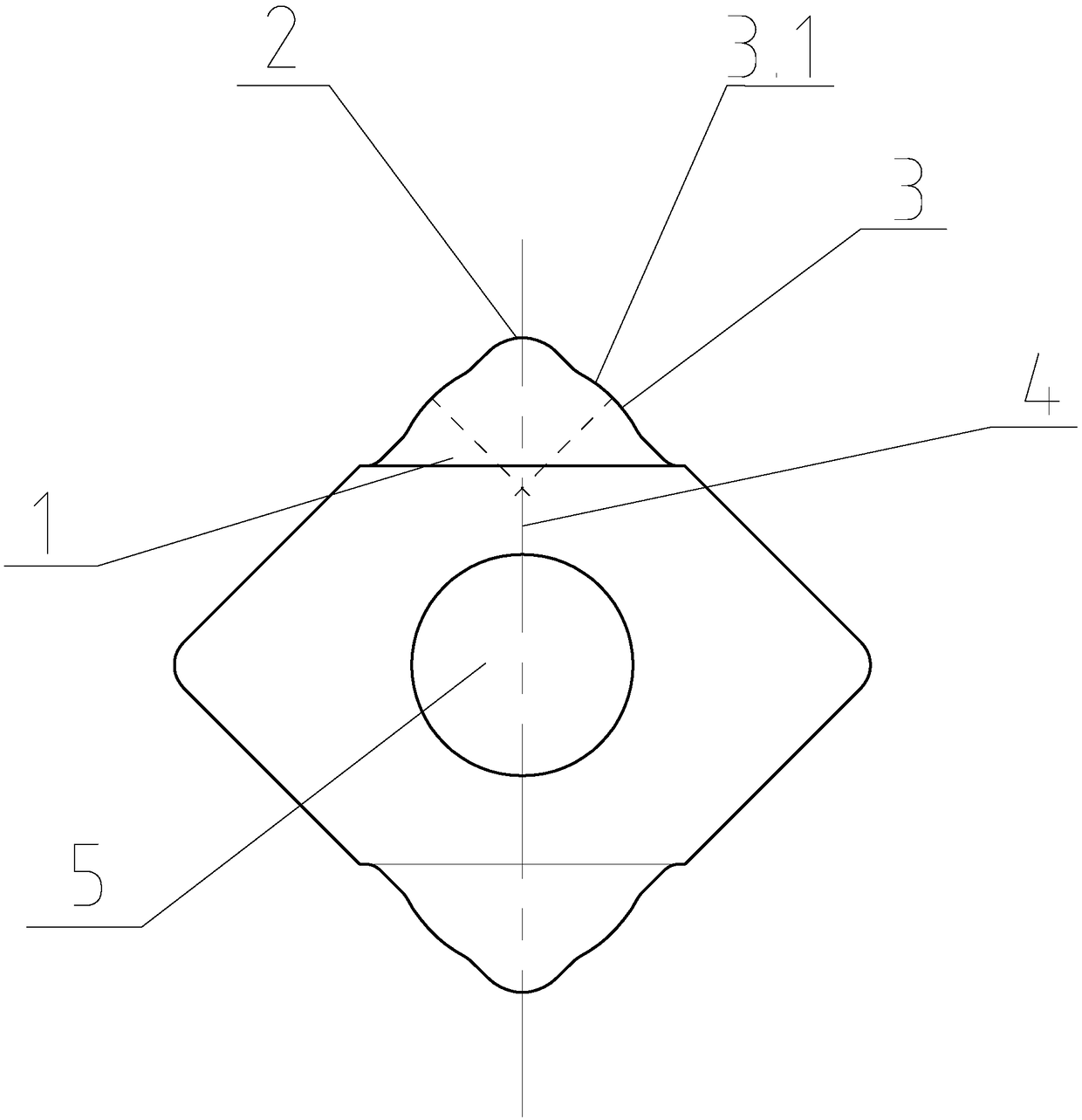
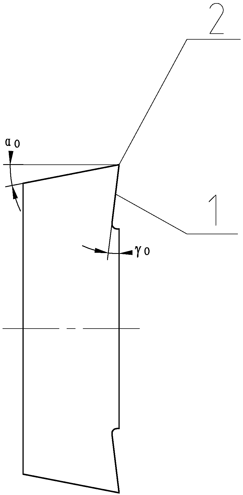
[0026] like Figure 1-2 As shown, a cutter head for processing ball screw thread includes a body, and the body includes two cutting edges 1, and the cutting edge 1 includes a cutting edge 2 and two side cutting edges 3, and the two side cutting edges 3 are connected to the cutting edge 2 and the body The line connecting the central points is left-right symmetrical. The side edge 3 includes a cutting protrusion 3.1, which is arc-shaped. The line connecting the sharp point of 2 and the central point of the body is the line of symmetry 4, the center of the cutting protrusion 3.1 on the left side of the line of symmetry 4 is on the right side of the line of symmetry 4, and the center of the cutting protrusion 3.1 on the right is on the left of the line of symmetry 4 Side, that is, the cutting protrusion 3.1 on the left side and the line connecting...


PUM


Abstract

The invention discloses a cutter bit for machining ball threads. The cutter bit comprises a body. The body comprises at least one cutting edge (1). The cutting edge (1) comprises a tool nose (2) and two side knife edges (3). The two side knife edges (3) are in bilateral symmetry about a connecting line of the sharp point of the cutting edge (2) and the center point of the body,. The two side knifeedges (3) are provided with cutting protrusions (3.1) correspondingly. The cutting protrusions (3.1) are in an arc shape. The invention further discloses a cutter. The cutter is characterized in thatthe cutter comprises a cutter fixing section (7) and a cutter bit fixing section (8); the cutter fixing section (7) and the cutter bit fixing section (8) are integrally connected; and the cutter bitfixing section (8) is detachably connected to the cutter bit for machining the ball threads. Through the cutter bit for machining the ball threads and the cutter, the production efficiency can be improved, the requirements of ball screw material selection is lowered, the machining loads of grinding are reduced, and the cutter bit is easy to replace.

Description

technical field [0001] The invention relates to the field of processing tools, in particular to a cutter head and cutter for processing ball threads. Background technique [0002] Ball threads generally appear on ball screws. Traditional ball threads are generally produced in two ways. One is the more commonly used cold rolling forming technology. The ball threads of the ball screw are directly formed by cold rolling, and then The two ends of the ball screw are turned or milled by means of heat treatment, such as the patent of publication number CN101224540A. There are many steps in the forming process of a ball screw, and there are strict requirements for the material selection of the ball screw. The different positions of the ball screw are processed by different processes, so that the production cycle of the ball screw is long; another way is to use the lathe to perform the turning process first, and then the grinding process, but the structure of the cutter head of the l...

Claims


Application Information

Patent Timeline
Patent Type & Authority Applications(China)
IPC IPC(8): B23B27/16
CPCB23B27/16
Inventor 任元平袁国智柏桂华
Owner NINGBO CHUANJINGYU MECHANICAL TECH DEV
Why Eureka
Try Eureka