
Ultrasonic fingerprint identification device and manufacturing method thereof and electronic device using ultrasonic fingerprint identification device

A technology of fingerprint recognition and ultrasonic wave, which is applied in the direction of using vibration fluid, character and pattern recognition, and acquiring/arranging fingerprints/palmprints, etc. It can solve manual removal, silver paste cannot be used as a mask, and silver paste cannot resist erosion, etc. problem, to achieve the effect of streamlining the production process

Active Publication Date: 2018-11-20
RECO TECH CHENGDU CO LTD
View PDF14 Cites 5 Cited by
  • Summary
  • Abstract
  • Description
  • Claims
  • Application Information

AI Technical Summary

Problems solved by technology

[0003] In the traditional structure, one electrode in the ultrasonic sensing unit in the ultrasonic fingerprint identification element is silver paste, and the thickness of the silver paste electrode is generally greater than 15 μm. The step difference is too large, and eventually the flexible circuit board is not easy to be directly lapped on the surface of the silver paste electrode
On the other hand, in the traditional structure, the piezoelectric layer is usually made by coating the piezoelectric material on the surface of the carrier substrate and etching and molding. When silver paste is used as the electrode, the silver paste cannot resist the erosion of conventional etching solution, making the silver paste It cannot be used as the mask of the piezoelectric material of the ultrasonic sensing unit during the etching process. The necessary mask needs to be set during the etching process of the piezoelectric material, and the mask needs to be removed manually.

Method used


Image

  • Ultrasonic fingerprint identification device and manufacturing method thereof and electronic device using ultrasonic fingerprint identification device
  • Ultrasonic fingerprint identification device and manufacturing method thereof and electronic device using ultrasonic fingerprint identification device
  • Ultrasonic fingerprint identification device and manufacturing method thereof and electronic device using ultrasonic fingerprint identification device

Examples


no. 1 example

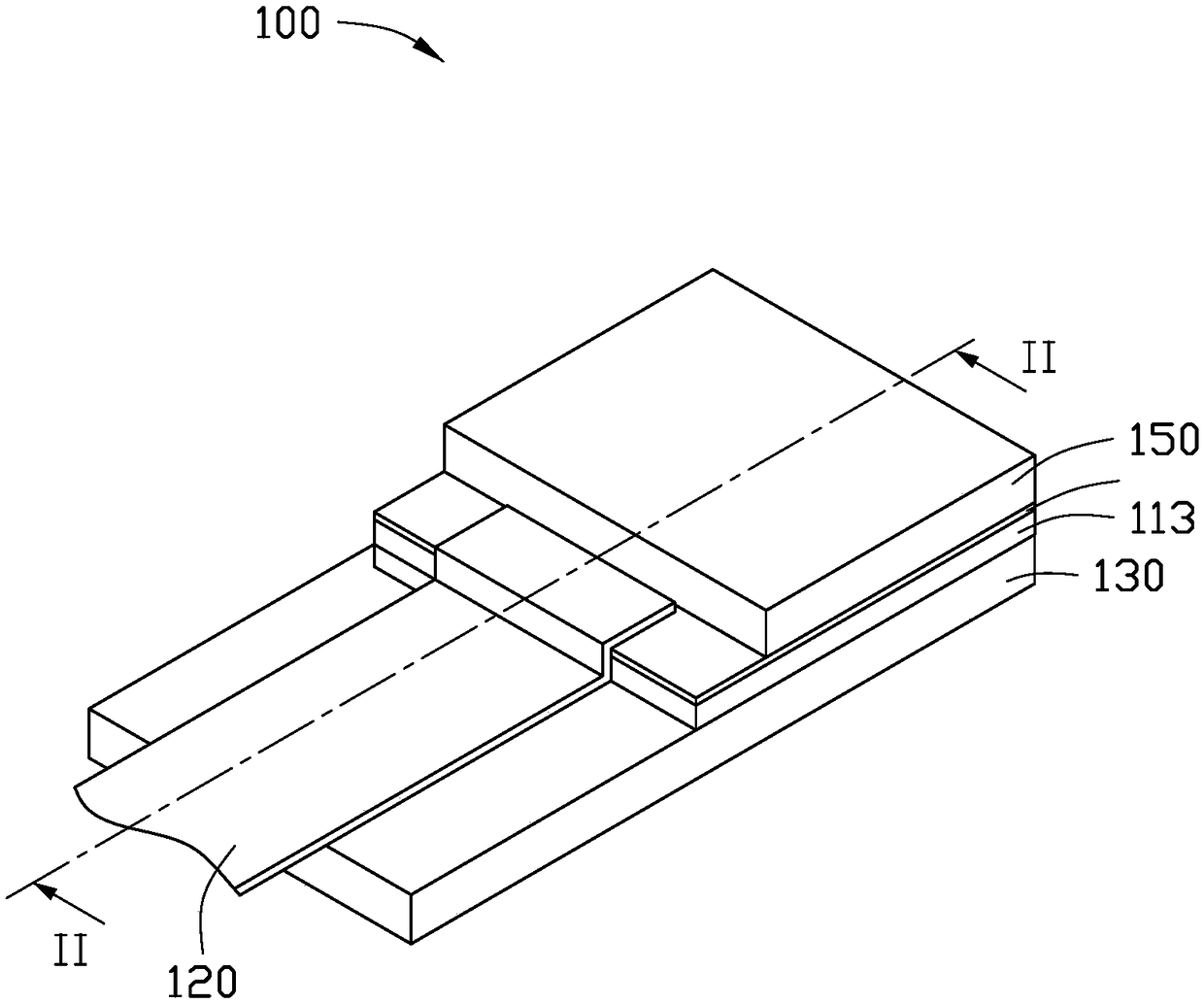
[0023] figure 1 It is a three-dimensional schematic diagram of an ultrasonic fingerprint identification device according to an embodiment of the present invention, figure 2 for figure 1 Schematic diagram of the section along II-II. Please also refer to figure 1 and figure 2 , the ultrasonic fingerprint identification device 100 according to the first embodiment of the present invention includes a circuit substrate 130 , an ultrasonic sensing unit 110 , and a signal transmission unit 120 .

[0024] A circuit substrate 130 is a carrier base, and the ultrasonic sensing unit 110 is arranged on one side of the circuit substrate 130. One end of the signal transmission unit 120 is connected to a control device (not shown), and the other end is connected to the ultrasonic sensing unit 110 and the circuit substrate 130 at the same time. In order to realize the signal transmission between the control device and the ultrasonic sensing unit 110 and the circuit substrate 130 .

[00...


PUM

PropertyMeasurementUnit
Thicknessaaaaaaaaaa

Abstract

The invention provides an ultrasonic fingerprint identification device comprising a circuit board substrate which includes the circuit; a piezoelectric layer which is arranged on one surface of the circuit substrate; a first electrode which is arranged on one side surface of the piezoelectric layer away from the circuit substrate, wherein the thickness range of the first electrode is from 0.005 mum to 1 mum; and a second electrode which formed on the circuit substrate and in contact with the surface of the piezoelectric layer away from the first electrode, wherein the piezoelectric layer is electrically connected to the circuit through the second electrode. The invention also provides a preparation method of the ultrasonic fingerprint identification device and an electronic device using the ultrasonic fingerprint identification device.

Description

technical field [0001] The invention relates to an ultrasonic fingerprint identification device, a manufacturing method thereof and an electronic device using the ultrasonic fingerprint identification device. Background technique [0002] With the widespread use of portable electronic devices, users have put forward more functional requirements for portable electronic devices. Due to the privacy protection function, the fingerprint identification device is installed in the portable electronic device to enhance user experience. Fingerprint identification devices can be divided into optical, capacitive, and acoustic wave types. Ultrasonic fingerprint recognition devices are widely used because their operation is not easily affected by ambient temperature and humidity, and they have long life and high resolution. The ultrasonic fingerprint identification element is the core element of the fingerprint identification device, which can identify the fingerprint of a finger placed...

Claims


Application Information

Patent Timeline
IPC IPC(8): G06K9/00H01L41/047H01L41/29H10N30/06H10N30/063H10N30/082H10N30/30H10N30/857H10N30/87H10N30/88
CPCG06V40/1306H10N30/87H10N30/06B06B1/0662H10N30/877H10N30/875H10N30/302H10N30/082B06B1/0644H10N30/872H10N30/063H10N30/88H10N30/857
Inventor 黄世杰
Owner RECO TECH CHENGDU CO LTD
Learn More