Eureka AIR delivers breakthrough ideas for toughest innovation challenges, trusted by R&D personnel around the world.

Array type ultrasonic dynamic sealing device and method

A sealing device and array technology, which is applied to the sealing of engines, engine components, mechanical equipment, etc., can solve the problems of not very severe sound pressure changes and unsatisfactory sealing effects, and achieve good results, convenient structure and assembly, and reduced The effect of wear and tear

Active Publication Date: 2018-11-20
XI AN JIAOTONG UNIV
View PDF4 Cites 1 Cited by
  • Summary
  • Abstract
  • Description
  • Claims
  • Application Information

AI Technical Summary

Problems solved by technology

[0003] Studies have shown that when there is a strong sound wave propagating in the medium, a non-periodic flow will often appear. This phenomenon is called acoustic flow. The ultrasonic sound flow effect is applied in the field of sealing technology to generate vortices in the sealing device. Furthermore, the kinetic energy of the fluid in the sealing gap is dissipated under the action of viscous resistance to achieve the purpose of reducing the leakage of the sealing device, but it should be noted that the sound pressure change caused by this phenomenon is not very drastic, and the sealing effect is not ideal , so it is necessary to propose a special sealing device to improve the sealing effect of the ultrasonic sealing device

Method used


Image

  • Array type ultrasonic dynamic sealing device and method
  • Array type ultrasonic dynamic sealing device and method
  • Array type ultrasonic dynamic sealing device and method

Examples


Embodiment

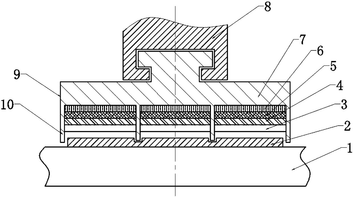
[0035] An array type ultrasonic dynamic sealing device of the present invention, the backing 6 is formed by hot pressing after fully mixing tungsten powder and epoxy resin, the particle size of the tungsten powder is 5 μm, and the volume fraction is 15%; the outer side of the backing 6 is in contact with the T-shaped groove, Fixed in the sealing sleeve 8 through the T-shaped groove;

[0036] Acoustoelectric chip belt 5 is made up of rectangular PZT piezoelectric ceramic sheet, and the thickness of piezoelectric ceramic sheet is 1 / 2 wavelength when ultrasonic wave propagates in it.

[0037] The matching layer 4 is made of low-viscosity epoxy resin filled with alumina in a single layer, the particle size of alumina powder is 2.5 μm, and the volume fraction is 25%. The filler and the base material are cast into a thin layer by casting. 1 / 4 wavelength when layer 4 propagates; acoustic lens 3 is made of polymethyl methacrylate (PMMA).

[0038] Four radial sealing teeth 10 are even...


PUM


Abstract

The invention discloses an array type ultrasonic dynamic sealing device and method. The device comprises a seal body, a seal cover and a gear shaft sleeve. The gear shaft sleeve is arranged on a sealing rotary shaft in a sleeving manner; the seal box comprises a gland sealing ring; the gland sealing ring is mounted on the periphery of the gear shaft sleeve, and a plurality of seal teeth are formedin a spaced manner on one side, opposite to the rotary shaft, of the gland sealing ring; a T-shaped groove is formed in the inner side of the T-shaped groove of the sealing cover; a T-shaped bump arranged in the side, far away from the rotary shaft, of the gland sealing ring is matched with the T-shaped groove of the sealing cover; independent sealing regions are formed between adjacent seal teeth; and each of the independent sealing regions formed between adjacent seal teeth is successively provided with an acoustic lens, a matching layer, an acoustoelectric wafer band and a backlining fromthe rotary shaft to outer side. Sound waves of the sealing regions are gathered in sealing gaps in the sealing regions. Media in the sealing gaps form relatively strong vortexes, and meanwhile, turbulent flow and choked flow action is generated to the media, and finally, kinetic energy of the media can be fully dissipated, so that the sealing effect of the sealing device is further improved.

Description

technical field [0001] The invention belongs to the technical field of sealing, in particular to a rotary mechanical dynamic sealing device and method. Background technique [0002] The research of dynamic sealing technology is of great significance in the fields of science and technology. With the development of industry, the operating environment of construction machinery has undergone profound changes, and its working conditions are becoming more and more demanding. It is moving towards extreme temperature, high corrosion, Development in the direction of high dust and micro scale. Traditional dynamic sealing technologies, such as packing seals, oil seals, labyrinth seals and mechanical seals, often fail to achieve the expected sealing effect in extreme working conditions. For example, packing seal, as a kind of contact seal, has the problem of wear and tear, and the packing needs to be replaced continuously; another example is oil film seal, whose sealing oil is greatly ...

Claims


Application Information

Patent Timeline
IPC IPC(8): F16J15/54
CPCF16J15/54
Inventor 高铁瑜李军杨博马晨曦曾俊雄龚建英尚伟张雄
Owner XI AN JIAOTONG UNIV
Why Eureka
Eureka Blog
Learn More