A self-locking power connector

A power connector, self-locking technology, applied in the direction of connection, parts of the connection device, contact parts, etc., can solve the problems of difficult connection, low efficiency, difficult to popularize and apply, etc., and achieve the effect of improving the efficiency of replacement and maintenance

Inactive Publication Date: 2020-03-17
厦门易上电子有限公司
View PDF4 Cites 0 Cited by
  • Summary
  • Abstract
  • Description
  • Claims
  • Application Information

AI Technical Summary

Problems solved by technology

The connection of these types of structures is relatively difficult when operated at the top, making it difficult to carry out corresponding popularization and application, especially in the field of lamps and lanterns. In the position, it will make the efficiency become low

Method used


Image

  • A self-locking power connector
  • A self-locking power connector
  • A self-locking power connector

Examples


Embodiment 1

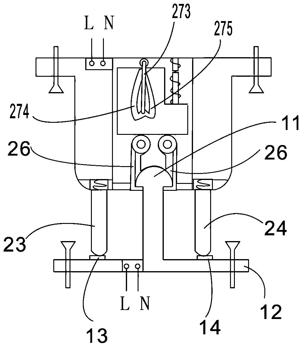
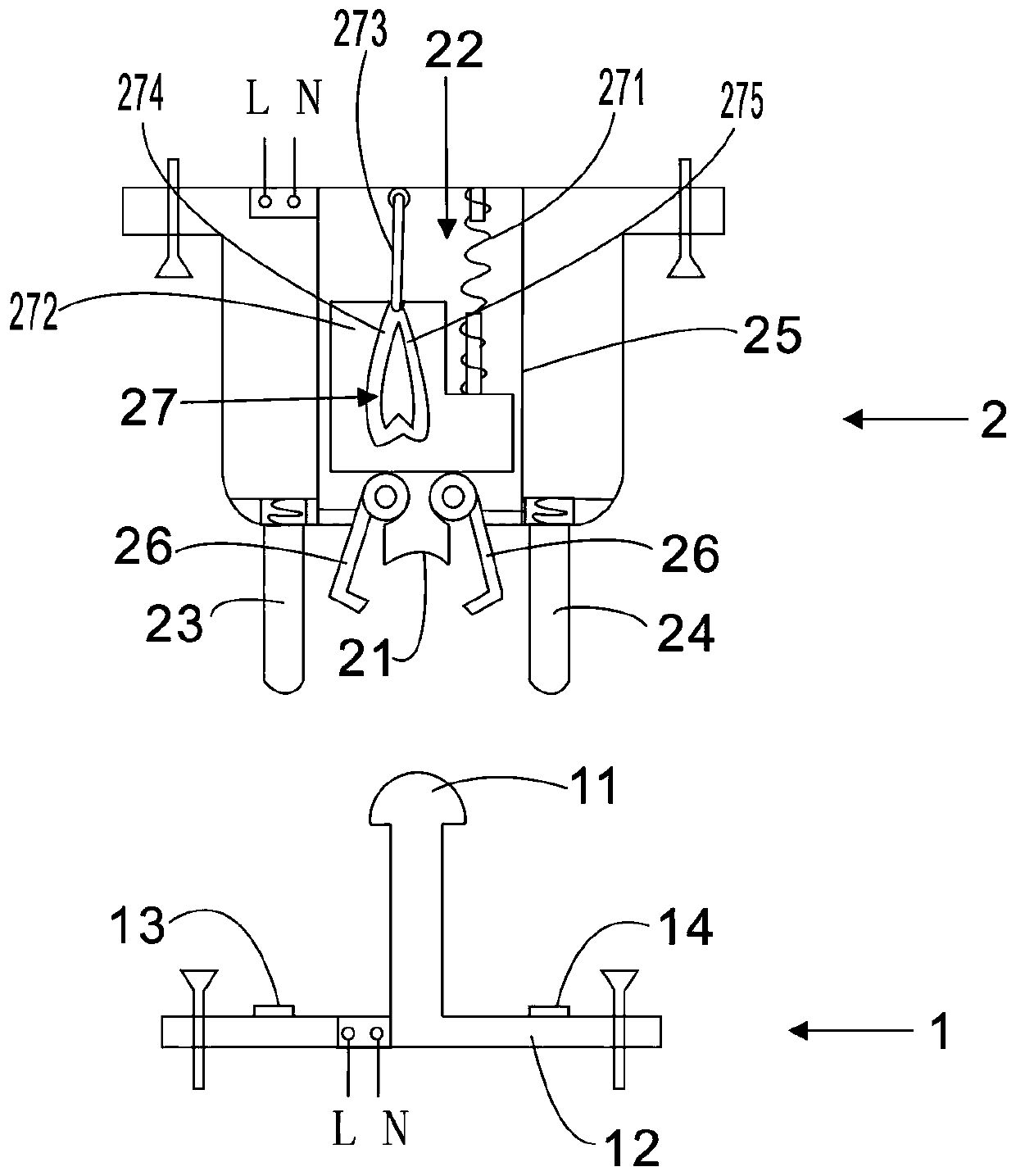
[0020] see figure 1 and figure 2 As shown, a self-locking power connector includes a fastener 1 and a clip 2 .

[0021] Among them, the fastener 1 is provided with a ball stud 11 and a contact plate 12 fixedly connected with the ball stud 11, and the touch plate 12 is provided with an N-level electrical contact piece 13 and an L-level electrical contact piece 14; The electric contact piece 13 and the L-level electric contact piece 14 are respectively located at both ends of the contact plate 12; the ball head part of the ball head protrusion can preferably be a hemispherical head.

[0022] The clip 2 is provided with an arc-shaped groove 21 for supporting the ball stud 11, and the both sides of the arc-shaped groove 21 are provided with movable clip devices 22; the two sides of the movable clip device are provided with N-level electric contacts 23 and L N-level electrical contact pin 24; N-level electrical contact pin 23 and L-level electrical contact pin 24 can be preferab...

Embodiment 3

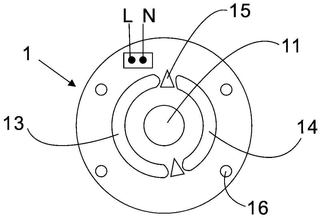
[0032] As another specific implementation, see image 3 As shown, the N-level electrical contact piece 13 and the L-level electrical contact piece 14 in this embodiment are surrounded by an arc, and a three-dimensional triangular plastic spacer 15 is provided between the N-level electrical contact piece 13 and the L-level electrical contact piece 14 . In this way, combined with the ball stud 11 (the ball head can be rotated arbitrarily), the fastener 1 can be fastened with the fastener 2 at almost any angle of 360 degrees. Wherein the effect of the three-dimensional triangular plastic spacer 15 is that the N-level electric contact pin and the L-level electric contact pin will naturally not be buckled when pushed against the three-dimensional triangular plastic spacer, which increases safety. At this time, the ball stud can be buckled up and contacted with the N-level electric contact piece and the L-level electric contact piece to turn on the power supply by slightly adjusting...


PUM


Abstract

The invention discloses a self-locking power connector, which comprises a fastener and a clip, wherein the fastener is provided with a ball head bump and a touch plate; the touch plate is provided with an N-level electric contact pad and an L-level electric contact pad; an arc-shaped groove for supporting the ball head bump is arranged in the clip; a movable clamp device is arranged at two sides of the arc-shaped groove; an N-level electric contact pin and an L-level electric contact pin are arranged at two sides of the movable clamp device; when the ball head bump presses the arc-shaped groove for the first time, the movable clamp device clamps the ball head bump, the N-level electric contact pin is in electric contact with the N-level electric contact pad and the L-level electric contactpin is in electric contact with the L-level electric contact pad to form self-locking; and when the ball head bump presses the arc-shaped groove for the second time, the movable clamp device bouncesoff the ball head bump, the N-level electric contact pin is separated from the N-level electric contact pad and the L-level electric contact pin is separated from the L-level electric contact pad to form unlocking. According to the self-locking power connector, self-locking and unlocking can be achieved through simple pressing, fixed connection and electric contact connection are achieved at the same time in self-locking, and removal and separation and electric separation are achieved at the same time in unlocking.

Description

technical field [0001] The invention relates to the technical field of lamp accessories, in particular to a self-locking power connector. Background technique [0002] At present, the power connector is commonly used for screw connection, and then an electrical contact is provided on the top of the thread; there are also those that do not use threads, but need to be rotated at a specific position, and then snapped on both sides. It is difficult to connect these structures when operating on the top, which makes it difficult to carry out corresponding popularization and application. Especially in the field of lamps, if the lamps located at high places are fixedly connected and electrically connected by rotation, it is difficult to rotate accurately In the position, the efficiency will become low. Contents of the invention [0003] In view of this, the purpose of the present invention is to provide a self-locking power supply connector, which can realize self-locking and unl...

Claims


Application Information

Patent Timeline
Patent Type & Authority Patents(China)
IPC IPC(8): H01R13/02H01R13/03H01R13/24H01R13/627H01R13/633H01R13/635H01R24/00
CPCH01R13/02H01R13/03H01R13/24H01R13/6275H01R13/633H01R13/635H01R24/005
Inventor 邱润洲
Owner 厦门易上电子有限公司
Why Eureka
Try Eureka