Anti-overheating separation device between dampening machine roller and driving system

A driving system and separation device technology, applied in the field of tobacco processing, can solve the problems affecting the normal operation of the moisture reconditioning machine, reduce the service life of the rubber sleeve, and accelerate the aging speed of the rubber, so as to improve the replacement and maintenance efficiency, facilitate the replacement and maintenance, and flexibly lower the reset reliable effect

Pending Publication Date: 2021-06-29
CHINA TOBACCO SHAANXI IND
View PDF0 Cites 0 Cited by
  • Summary
  • Abstract
  • Description
  • Claims
  • Application Information

AI Technical Summary

Problems solved by technology

At present, the drum of the silk resurfacing machine is placed at an inclination of 3°-5°, supported by two sets of support wheels at both ends, and two drive motors are respectively connected to the rotating shaft at the lower end of the drum to drive the support wheels to rotate, thereby driving the drum to rotate. In order to increase the friction between the support wheel and the drum, and to facilitate the rotation of the drum, a rubber sleeve is specially installed on the support wheel, so as to ensure the smooth and effective transmission of power to the drum to the greatest extent; After processing the shredded tobacco, the temperature inside the damper is still relatively high. When the production is over, the drum stops rotating, and the high temperature on the outer wall of the drum will directly act on the rubber sleeve, which accelerates the aging speed of the rubber and reduces the service life of the rubber sleeve. Affect the normal drive of the drum, and when the drum stops running for a long time, the whole weight will drop directly on a fixed point of the rotating shaft. After a long time, it will cause rubber deformation, make the subsequent rotation not smooth, and increase the aging of the rubber sleeve. Deformation causes equipment failure and affects the normal operation of the dampening machine. Therefore, it is necessary to improve the above problems

Method used


Image

  • Anti-overheating separation device between dampening machine roller and driving system
  • Anti-overheating separation device between dampening machine roller and driving system

Examples


Embodiment Construction

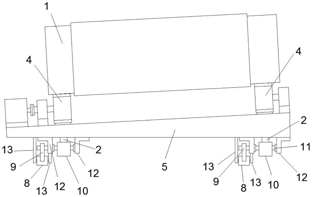
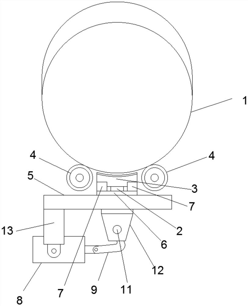
[0021] Attached below Figure 1-2 An embodiment of the present invention is described so as to clearly and completely describe the technical solution. Obviously, the described embodiment is only a part of the embodiments of the present invention, rather than all the embodiments.

[0022] In describing the present invention, it should be understood that the terms "upper", "lower", "front", "rear", "left", "right", "top", "bottom", "inner", " The orientation or positional relationship indicated by "outside", etc. is based on the orientation or positional relationship shown in the drawings, which is only for the convenience of describing the present invention and simplifying the description, rather than indicating or implying that the referred device or element must have a specific orientation, so as to Specific orientation configurations and operations, therefore, are not to be construed as limitations of the invention.

[0023] The anti-overheating separation device between th...


PUM


Abstract

The invention provides an anti-overheating separation device between a dampening machine roller and a driving system, a jacking column is located between two driving supporting wheels which make contact with the bottom of the dampening machine roller and drive the dampening machine roller to rotate, and a top plate with the upper end face being the same as the dampening machine roller in radian is fixed to the upper end of the jacking column. The lower end of the jacking column penetrates through a dampening machine rack, the descending position of the jacking column is positioned through a positioning assembly arranged on the upper end face of the dampening machine rack, and a driving device is arranged on the bottom face of the dampening machine rack and drives the jacking column to ascend or descend. The top plate is driven to jack the dampening machine roller to be separated from the driving supporting wheels or to enable the dampening machine roller to be in contact with the driving supporting wheels. The problem that when the dampening machine stops, the temperature of the roller is too high, and consequently rubber sleeves on the outer layer of the driving supporting wheels are affected is solved, the service life of the driving supporting wheels is prolonged, the equipment failure rate caused by failure or aging of the rubber sleeves is reduced, the structure is simple, the installation is convenient and fast, and the overheating prevention effect is good.

Description

technical field [0001] The invention belongs to the technical field of tobacco processing, and in particular relates to an overheating prevention separation device between a moisture conditioner drum and a driving system. Background technique [0002] During the processing and manufacturing process of shredded tobacco, the moisture content of shredded tobacco is about 18% after passing through the shredding machine, and then transported to the roller-type shredded shred moisture conditioner by quantitative conveying equipment. Increase to 20%-22%, and the outlet temperature is about 40-60 degrees Celsius, so that it can meet the technological requirements of the expansion function of the silk drying equipment. At present, the drum of the silk resurfacing machine is placed at an inclination of 3°-5°, supported by two sets of support wheels at both ends, and two drive motors are respectively connected to the rotating shaft at the lower end of the drum to drive the support whee...

Claims


Application Information

Patent Timeline
Patent Type & Authority Applications(China)
IPC IPC(8): A24B3/04
CPCA24B3/04
Inventor 徐玉良雷刚方玉宏秦浩寇东玲
Owner CHINA TOBACCO SHAANXI IND
Why Eureka
Try Eureka