
A magnetron hot wire swing laser welding device, method and application

A technology of oscillating laser welding and hot wire, applied in laser welding equipment, welding equipment, metal processing equipment, etc., can solve the problems of poor applicability, clumsy equipment, and difficulty in achieving the desired effect in molten pool control, and achieve strong practicability , reduce the unfused side wall, alleviate the effect of welding crack defects

Active Publication Date: 2021-01-05
HARBIN INST OF TECH AT WEIHAI
View PDF13 Cites 0 Cited by
  • Summary
  • Abstract
  • Description
  • Claims
  • Application Information

AI Technical Summary

Problems solved by technology

The magnetic field application equipment is clumsy and has poor applicability, especially for welding processes such as narrow gaps. It is difficult to achieve the desired effect on the control of the molten pool by an external magnetic field, and it is difficult to effectively control defects in the welding process. to regulate

Method used


Image

  • A magnetron hot wire swing laser welding device, method and application
  • A magnetron hot wire swing laser welding device, method and application
  • A magnetron hot wire swing laser welding device, method and application

Examples


Embodiment 1

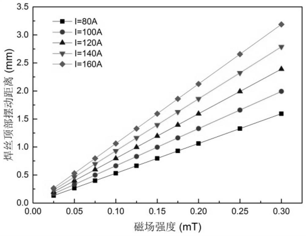
[0052] 1. Use plate surfacing to verify the influence of magnetron heating wire on joint forming. Using welding wire with a diameter of 1.2mm, the dry elongation of the welding wire is controlled at 20-40mm, the heating current of the hot wire is 80-100A, the wire feeding angle is 45°, the wire feeding speed is 2.5m / min, and the size of the permanent magnet device is 60mm *20mm*5mm, the magnetic field strength generated at the hot wire position is about 80-140mT, and the resulting welding wire deflection distance is about 1.0mm.

[0053] 2. The welding wire adopts the front wire feeding method, the shielding gas adopts pure Ar, the gas flow rate is 15L / min, and the rear gas supply is used to send the shielding gas pipe to the groove gap to protect the welding pool metal.

[0054] 3. The fiber laser is adopted, the laser power is 4000W, the welding speed is 1.5m / min, the laser is a continuous laser output, and the high-speed camera is used to observe the droplet transition beha...

Embodiment 2

[0056] 1. The stainless steel plate with a thickness of 50mm is notched, the blunt edge thickness B=3-4mm; the root gap P=2mm; the bottom groove spacing S=0.5-1.5mm; the groove angle β=2-4°. The stainless steel adopts the butt joint form, and the base metal to be welded is fixed by a clamp.

[0057] 2. Use welding wire with a diameter of 1.2mm, the dry elongation of the welding wire is controlled at 15-30mm, the heating current of the hot wire is 120-160A, the wire feeding angle is 45°, the wire feeding speed is 2.5m / min, and the size of the permanent magnet device is added. It is 60mm*20mm*5mm, the magnetic field intensity generated at the hot wire position is about 60-120mT, and the resulting welding wire deflection distance is about 0.5mm.

[0058] 3. The welding wire adopts the front wire feeding method, the shielding gas adopts pure Ar, the gas flow rate is 15L / min, and the rear gas supply is used to send the shielding gas pipe to the groove gap to protect the welding poo...


PUM

PropertyMeasurementUnit
magnetic flux densityaaaaaaaaaa
thicknessaaaaaaaaaa
lengthaaaaaaaaaa

Abstract

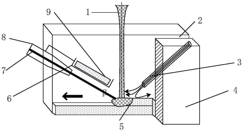
The invention discloses a magnetically controlled hot wire swing laser welding device and method, which includes applying an external magnetic field generated by a permanent magnet on the hot wire, and the interaction between the external magnetic field and the hot wire current will generate an ampere force, and change the feeding mode of the hot wire ; Control the swing range of the hot wire by adjusting the strength of the magnetic field device, the current of the hot wire and the heating length of the hot wire. On the one hand, the swing of the hot wire can change the distribution of the heat source in the molten pool, realize the control of the weld shape, and improve the poor fusion of the narrow gap welding side wall; on the other hand, the swinging welding wire can stir the welding pool to a certain extent, Refine the weld structure. The enhanced fluidity of the molten pool can also suppress the occurrence of defects such as welding pores and cracks, thereby improving the performance of the welded joint. The device of the invention has the advantages of simple structure, flexible operation and strong adaptability.

Description

technical field [0001] The invention relates to the field of laser welding, in particular to a magnetron heating wire swing laser welding device, method and application. Background technique [0002] In the narrow gap welding process of laser medium and thick plates, due to the small heating area of ​​the laser spot, it often leads to defects of unfused side walls of the groove, and the cooling speed is fast during the welding process, and defects such as welding pores and cracks are prone to occur, thereby reducing performance of welded joints. By applying an external magnetic field to the weld pool and interacting with the induced current or external current generated by the weld pool, the convection of the liquid metal in the weld pool is enhanced, and the grains of the weld metal are refined; and the temperature gradient is reduced to suppress the occurrence of welding cracks. In turn, the defects of welded joints can be improved, and the performance of joints can be im...

Claims


Application Information

Patent Timeline
Patent Type & Authority Patents(China)
IPC IPC(8): B23K26/70B23K26/21
CPCB23K26/21B23K26/70B23K26/702
Inventor 孙清洁李军兆刘一搏甄祖阳康克新冯吉才
Owner HARBIN INST OF TECH AT WEIHAI
Learn More