Automatic stamping equipment

A technology of stamping equipment and stamping grooves, which is applied in the direction of launching equipment, metal processing equipment, chemical instruments and methods, etc., can solve the problems of reducing the service life of molds, unfavorable automation, and long processing cycles, so as to prolong the service life and save labor costs , Improve the effect of supporting ability

Pending Publication Date: 2018-11-16
SUZHOU HONGQIRUI AUTOMATION
View PDF0 Cites 3 Cited by
  • Summary
  • Abstract
  • Description
  • Claims
  • Application Information

AI Technical Summary

Problems solved by technology

[0002] In the prior art, a stamping machine is used to process the parts, and the parts are stamped and formed by the stamping machine, while manual operation is used in the feeding and discharging process of the stamping machine, and the parts to be stamped are manually put into the stamping process of the stamping machine. In the mold, it is stamped by the punch of the stamping mechanism. After the stamping is completed, it is manually taken out of the stamping mold and stamped by manual feeding, which will lead to a high risk factor, low production efficiency, and high labor costs. , In addition, the parts are manually fed into the punching machine, the process is not easy to control, the quality assurance of the product cannot be realized, and the processing cycle is long, which is not conducive to the automation of the subsequent process. In addition, the mold is subjected to a large impact force during stamping, which will cause Cracks in the mold reduce the service life of the mold

Method used


Image

  • Automatic stamping equipment
  • Automatic stamping equipment
  • Automatic stamping equipment

Examples


Embodiment Construction

[0017] The preferred embodiments of the present invention will be described below in conjunction with the accompanying drawings. It should be understood that the preferred embodiments described here are only used to illustrate and explain the present invention, and are not intended to limit the present invention.

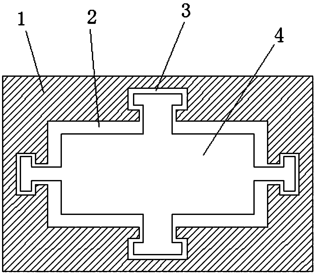
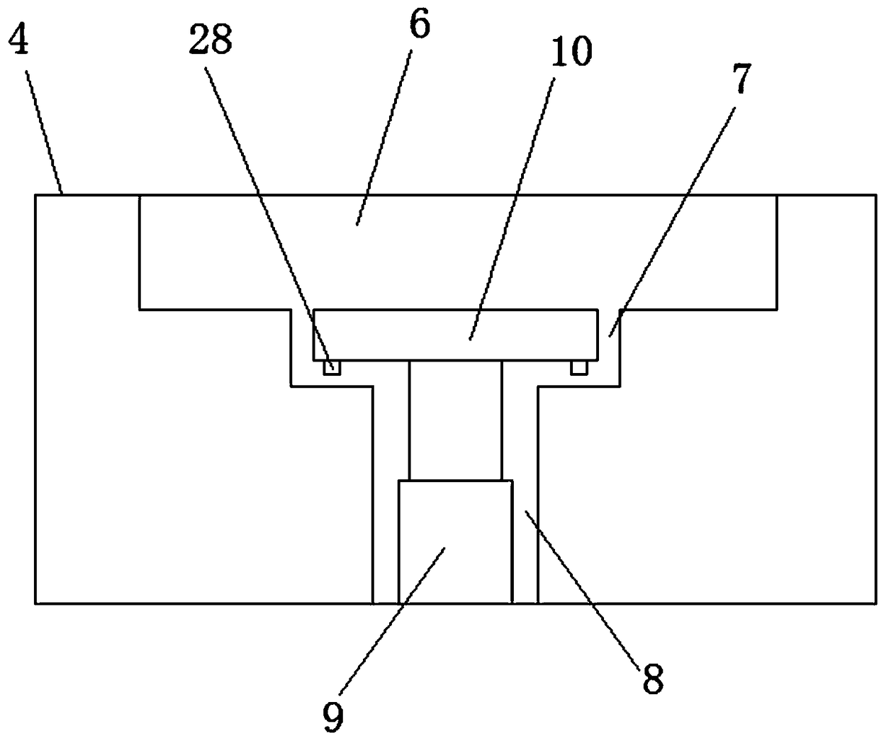
[0018] see Figure 1-Figure 4 , the present invention provides a technical solution: an automatic stamping equipment, including a workbench 1, a buffer tank 2 is provided on the top of the workbench 1, a chute 3 is provided on the inner wall of the buffer tank 2, and the chute 3 passes through The slider is slidably connected with a lower die 4, and the bottom of the lower die 4 is connected to the workbench 1 through a buffer spring 5 to reduce the impact force on the lower die 4. The top of the lower die 4 is provided with a punching groove 6, and the punching groove 6 bottom is provided with groove 7, and described groove 7 bottom is provided with vertical groove...


PUM


Abstract

The invention relates to automatic stamping equipment. The automatic stamping equipment comprises a working platform, a buffer slot is formed in the top of the working platform, and a sliding groove is formed in the buffer slot. A lower mould is connected to the sliding groove in a sliding mode through a sliding block, and the working platform is connected to the bottom of the lower mould througha buffer spring. A stamping groove is formed in the top of the lower mould, a groove is formed in the bottom of the stamping groove, and a vertical slot is formed in the bottom of the groove. A firsthydraulic cylinder is installed in the vertical slot, wherein a push plate is fixedly connected to the top of the first hydraulic cylinder, and the push plate is arranged in the groove. Through the arrangement of the buffer spring, the impact force to moulds is reduced when stamping, and the service life of the moulds is conveniently prolonged; through arranging the push plate, workpiece after stamping is pushed out, and blanking is convenient to carry out; through arranging air holes, impurities inside the stamping groove are blew away, and the product quality affected is avoided; through arranging blanking pieces, automatic blanking is carried out, and the labor cost is conveniently saved.

Description

technical field [0001] The invention relates to an automatic stamping equipment, which belongs to the technical field of stamping equipment. Background technique [0002] In the prior art, a stamping machine is used to process the parts, and the parts are stamped and formed by the stamping machine, while manual operation is used in the feeding and discharging process of the stamping machine, and the parts to be stamped are manually put into the stamping process of the stamping machine. In the mold, it is stamped by the punch of the stamping mechanism. After the stamping is completed, it is manually taken out of the stamping mold and stamped by manual feeding, which will lead to a high risk factor, low production efficiency, and high labor costs. , In addition, the parts are manually fed into the punching machine, the process is not easy to control, the quality assurance of the product cannot be realized, and the processing cycle is long, which is not conducive to the automat...

Claims


Application Information

Patent Timeline
IPC IPC(8): B21D22/02B21D37/10B21D45/02B08B5/02
CPCB08B5/02B21D22/02B21D37/10B21D45/02
Inventor 曾胜兴
Owner SUZHOU HONGQIRUI AUTOMATION
Why Eureka
Try Eureka