Earth dielectric spectrum detecting method
A detection method and dielectric spectrum technology, applied in dielectric performance measurement, seismic measurement, geophysical measurement, etc., can solve problems such as the existence of the geodetic electric field, large electrode distance, interference factors, etc., to eliminate non-precursor interference, device The system is simple and the effect of broad application prospects
- Summary
- Abstract
- Description
- Claims
- Application Information
AI Technical Summary
Problems solved by technology
Method used
Image
Examples
Embodiment 1
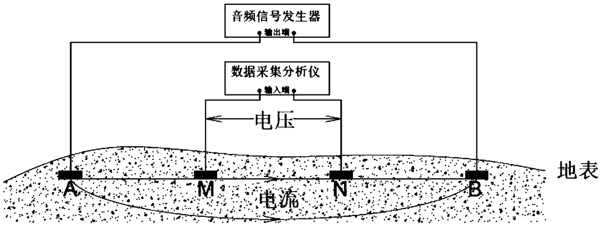
[0064] The dielectric spectrum observation device is deployed in the survey area. Such as figure 1 As shown, the observation device consists of four electrodes and their connecting wires, an audio signal generator, and a data acquisition analyzer. Four electrodes are used to overcome the effect of electrode polarization. Among the four electrodes, A and B are a pair of power supply electrodes, which supply excitation current of a specific frequency to the two electrodes of A and B, and M and N are a pair of measurement electrodes, which are connected to a data analyzer with high input impedance.
[0065] Main Specifications:
[0066] Frequency range: 20Hz~20kHz;
[0067] Input impedance of data acquisition device: input resistance value ≥ 1GΩ, input capacitance ≤ 100pf;
[0068] The maximum allowable error of voltage measurement: ±(0.02% of reading+300uV)@20℃;
[0069] Voltage measurement resolution: ±20uV(DC)@1V;
[0070] Current measurement resolution: ±20uA(DC)@1A;
...
Embodiment 2
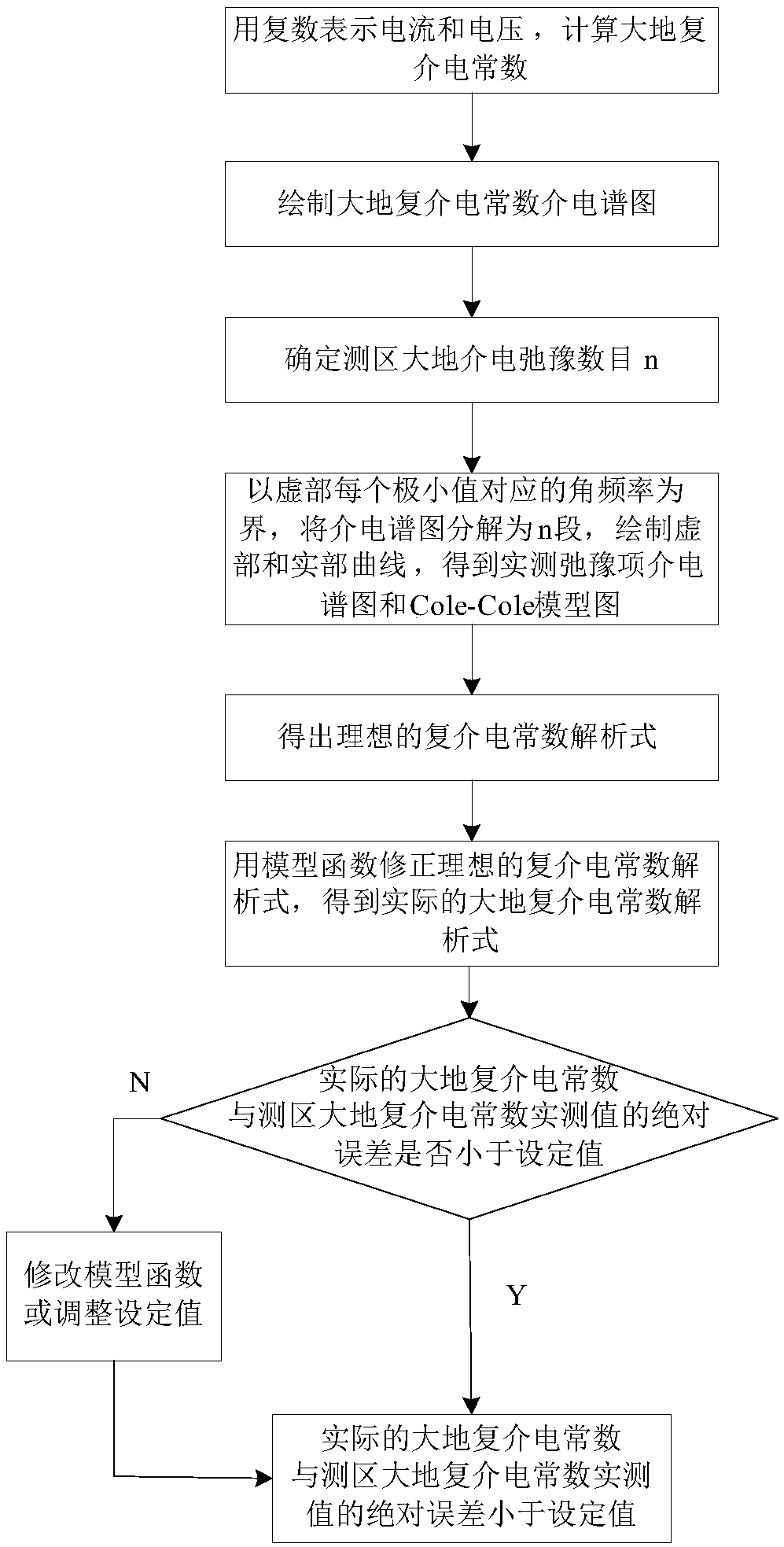
[0081] This embodiment introduces a method of utilizing the device in Embodiment 1 to detect the dielectric spectrum of the earth, such as figure 2 As shown, specifically:
[0082] Step 1, using the dielectric spectrum detection device to collect survey area data, including the current passing through the power supply electrode and the voltage on the measurement electrode;
[0083] Step 2. Draw the dielectric spectrum of the survey area, including:
[0084] (1) Use complex numbers to express the measured voltage and current, and calculate the earth complex permittivity value of each measurement frequency point f in the measurement area, which is divided into real part and imaginary part (ε, ε″);
[0085] (2) Draw the dielectric spectrum diagram of the complex permittivity of the earth in the survey area, the abscissa axis is the angular frequency ω=2πf, and the ordinate is the real part and the imaginary part respectively;
[0086] Step 3. According to the number of maximum...
Embodiment 3
[0100] The difference from Example 2 is that the number of earth dielectric relaxations in the survey area is determined to be n=3. At this time, the dielectric relaxations are the relaxation of the superficial and shallow soil medium, the relaxation of the lower layer rocks and the ion polarization relax.
[0101] at this time,
[0102] Step 4, decompose the dielectric spectrum into three, and perform the following operations on the dielectric spectrum:
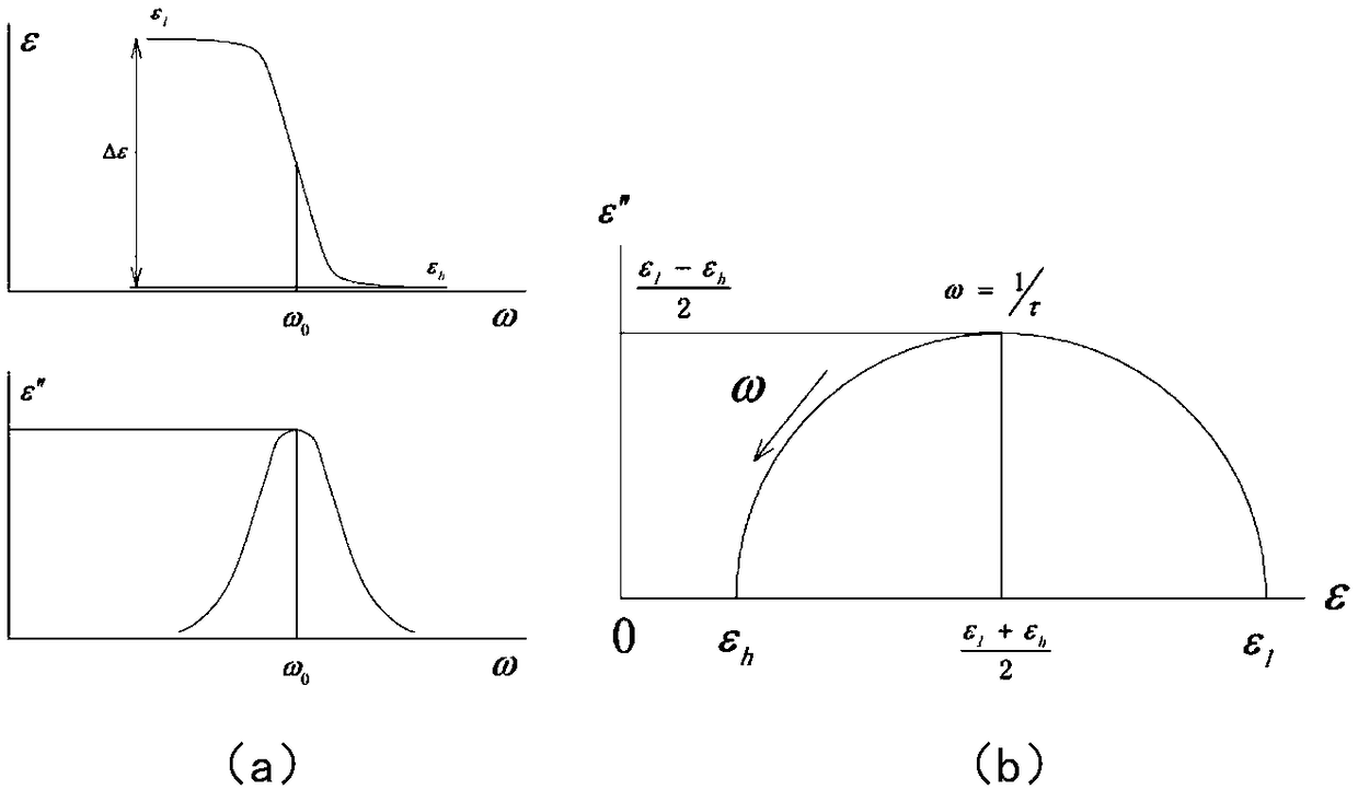
[0103] Find the angular frequency point ω corresponding to each maximum value of the imaginary part O1 ,ω O2 ,ω O3 , which is the relaxation angular frequency;
[0104] Find each minimum value of the imaginary part, divide the dielectric spectrum into three frequency bands with the angular frequency point corresponding to the minimum value as the boundary, and draw the curves of the imaginary part respectively. The imaginary part of the dielectric constant is at the lowest electromagnetic frequency The value is denoted ...
PUM
 Abstract
Description
Claims
Application Information
 - R&D
- Intellectual Property
- Life Sciences
- Materials
- Tech Scout
- Unparalleled Data Quality
- Higher Quality Content
- 60% Fewer Hallucinations
Browse by: Latest US Patents, China's latest patents, Technical Efficacy Thesaurus, Application Domain, Technology Topic, Popular Technical Reports.
© 2025 PatSnap. All rights reserved.Legal|Privacy policy|Modern Slavery Act Transparency Statement|Sitemap|About US| Contact US: help@patsnap.com


