
Burner with burning knob and flame continuous control method based on burning knob

A control method and burner technology, applied to gas fuel burners, burners, combustion methods, etc., can solve problems such as continuous combustion control, avoid high-temperature pollutants, avoid high-temperature damage, and achieve the effect of flame regulation

Pending Publication Date: 2018-11-13
SICHUAN TIANFA TECH
View PDF0 Cites 0 Cited by
  • Summary
  • Abstract
  • Description
  • Claims
  • Application Information

AI Technical Summary

Problems solved by technology

[0003] The invention provides a burner with a combustion knob, the purpose of which is to solve the problem that the traditional combustion cannot be continuously controlled, and to use an external continuous laser or an electric heating device to continuously control the combustion and realize the dynamic and continuous adjustment of the flame

Method used


Image

  • Burner with burning knob and flame continuous control method based on burning knob
  • Burner with burning knob and flame continuous control method based on burning knob

Examples


Embodiment Construction

[0026] In order to illustrate the technical solution of the present invention more clearly, the accompanying drawings that need to be used in the description will be briefly introduced below. Obviously, the accompanying drawings in the following description are only some embodiments of the present invention. As far as people are concerned, other embodiments can also be obtained according to these drawings on the premise of not paying creative work.

[0027] The specific implementation manner of the present invention will be described below in conjunction with the accompanying drawings.

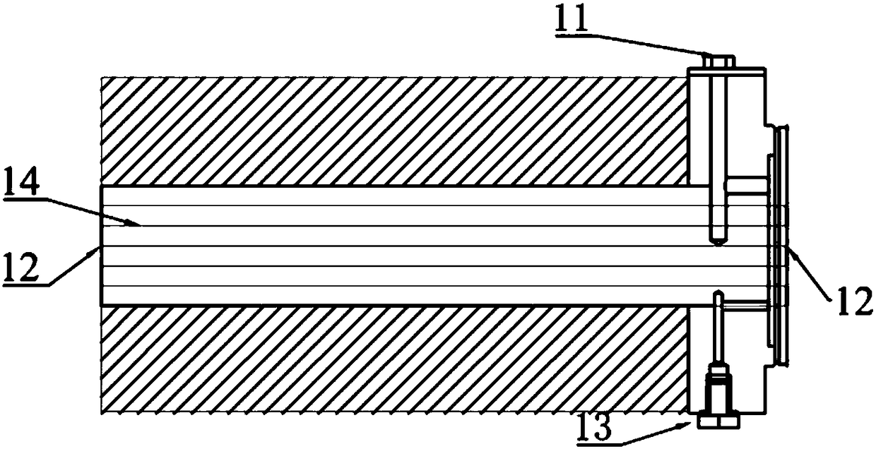
[0028] Such as figure 2 Shown:

[0029] The burner of the present invention has the burner passage 14 that is made of porous medium ceramic material; Extinguishing grid 12 (for example metal grid sheet) is installed in burner inlet and outlet; 11 is a silicon-molybdenum material electric heating rod, and a temperature detection device 13 is also arranged in the burner, and the temperature d...


PUM


Abstract

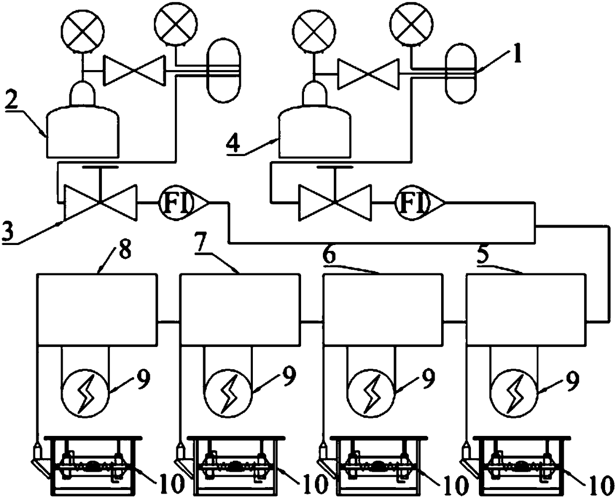
The invention provides a burner with a burning knob. The burner is characterized in that the burner is provided with a burner channel made of a porous medium ceramic material; flameout grids are mounted at an inlet or an outlet of the burner; the burner is internally provided with an electric heating device; the electric heating device is connected with an electric heating power adjusting device;and the electric heating device and the electric heating power adjusting device constitute the electric heating burning knob. The burner is provided with a laser device. The laser device emits laser in the radial direction of the burner, namely, from the inlet of the burner to the outlet of the burner, or from the outlet of the burner to the inlet of the burner. The laser device is connected witha laser power adjusting device. The laser device and the laser power adjusting device constitute a laser burning knob. The invention further provides a flame continuous control method based on the burning knob. The burner conducts continuous control over burning through the external continuous laser or electric heating device to implement dynamic continuous adjustment on flames.

Description

technical field [0001] The invention relates to a burner and also relates to a flame control method. Background technique [0002] The traditional combustion control technology continuously changes the size of the flame by adjusting the fuel flow rate, which is essentially to adjust the flame volume, and the dynamic state of the flame itself is in an uncontrollable state due to the positive feedback effect of combustion heat release. Uncontrollable combustion can only be controlled in two stages of ignition and extinguishment. The release of combustion heat cannot be flexibly controlled, and high-temperature combustion will cause damage to equipment. Contents of the invention [0003] The invention provides a burner with a combustion knob, which aims to solve the problem that traditional combustion cannot be continuously controlled, and uses an external continuous laser or an electric heating device to continuously control the combustion to realize dynamic and continuous a...

Claims


Application Information

Patent Timeline
Patent Type & Authority Applications(China)
IPC IPC(8): F23D14/02F23D14/46F23D14/72
CPCF23D14/02F23D14/46F23D14/72
Inventor 汪洋周俊虎姚亮张永亮陈永川刘树刚文光旭张江林潘宏春周容
Owner SICHUAN TIANFA TECH
Learn More