
Multi-directional positioning stamping die

A stamping die, multi-directional technology, applied in the field of stamping die with multi-directional positioning, can solve the problems of inaccurate positioning of the upper stamping die and the lower stamping die, the buffering effect of the difficult stamping die, and accurate positioning, etc. The effect of working hours and improving work efficiency

Active Publication Date: 2018-11-13
深圳市联华懿盛实业有限公司
View PDF8 Cites 5 Cited by
  • Summary
  • Abstract
  • Description
  • Claims
  • Application Information

AI Technical Summary

Problems solved by technology

[0003] A Chinese patent discloses a rapid prototyping mobile phone case stamping die (authorized notification number CN107138614A). The rapid prototyping mobile phone case stamping die provided by this patent technology has a rapid prototyping function, and the mobile phone case formed by the stamping die has One-time forming inner buckle hemming structure, the stamping die has simple structure, high work efficiency, reduced manufacturing process, and saved manufacturing cost, but it is difficult to make the positioning between the upper stamping die and the lower stamping die more accurate, resulting in the upper The positioning between the stamping die and the lower stamping die is inaccurate, causing the die after stamping to fail to meet the production requirements. Re-stamping the die is time-consuming and labor-intensive, increasing the working hours of the staff, making it difficult to eject the die after stamping from the die export mechanism, and It is difficult to play a certain cushioning effect on the stamping die, and it is difficult to push the ejected stamping die product into the collection box. When the staff uses their hands to pick up the stamping die product, the upper stamping die descends and squeezes the staff's fingers , injuring workers

Method used


Image

  • Multi-directional positioning stamping die
  • Multi-directional positioning stamping die
  • Multi-directional positioning stamping die

Examples


Embodiment Construction

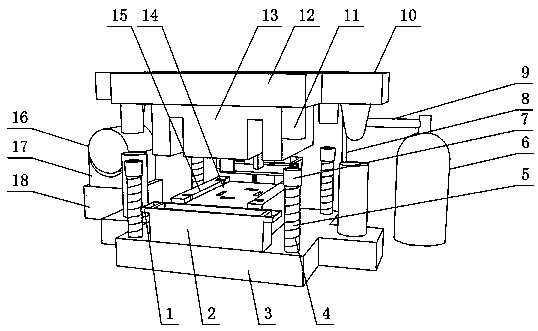
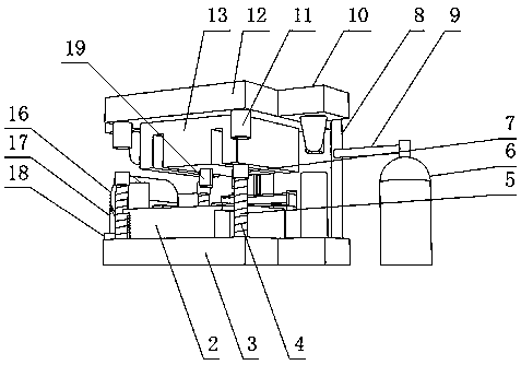
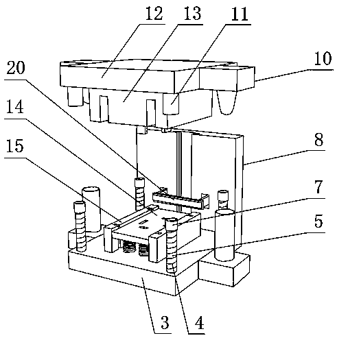
[0028] see Figure 1~6 , in an embodiment of the present invention, a stamping die with multi-directional positioning includes a stamping die body 12, an upper stamping die 13 is fixedly installed on the bottom of the stamping die body 12, and the bottom of the stamping die body 12 is close to one of the upper stamping dies 13 Positioning slots 11 are welded at the side position, grooves are provided on the lower surface of the upper stamping die 13, the grooves are used in conjunction with the lower stamping die 15, and the number of the grooves is two, the rear side of the stamping die body 12 is slidingly connected There is a back plate 8, and the two sides of the stamping die body 12 are fixedly equipped with a chute-type positioning mechanism 10, the inside of the back plate 8 is provided with a cross-shaped groove, and the rear side of the stamping die body 12 is fixedly equipped with a cross-shaped projection. The sliding connection between the back plate 8 and the stam...


PUM


Abstract

The invention discloses a multi-directional positioning stamping die. The multi-directional positioning stamping die comprises a stamping die body. A die export mechanism is slidably connected to theinner portion of a lower stamping die. One ends of positioning columns are connected with positioning top caps in a sleeved mode, and the outer sides of the positioning columns are connected with first springs in a sleeved mode. One end of a hydraulic tube is connected with a hydraulic tank in a threaded mode. One side of a pushing mechanism is rotatably connected with a vibration motor. A base isarranged at the bottom of the vibration motor, and a base plate is connected to the bottom end of the base in a threaded mode. Through the combined use of a top block, a positioning cone, a positioning cone groove, a partition plate, a positioning cone shell, a second spring and a bottom block, positioning between an upper stamping die and the lower stamping die can be more precise, and the problems that dies after stamping do not meet the production requirements and need to be re-stamped, time and labor are wasted, and the labor hour of staff is increased due to the fact that positioning between the upper stamping die and the lower stamping die is not accurate are solved.

Description

technical field [0001] The invention relates to the technical field of dies, in particular to a stamping die with multi-directional positioning. Background technique [0002] Stamping die is a special process equipment for processing materials (metal or non-metal) into parts (or semi-finished products) in cold stamping processing. It is called cold stamping die (commonly known as cold stamping die). Stamping is installed at room temperature The mold on the press presses the material to cause separation or plastic deformation to obtain a press processing method for the required parts. The materials for manufacturing stamping molds include steel, hard alloy, steel-bonded hard alloy, and zinc-based Alloys, low-melting point alloys, aluminum bronze, polymer materials, etc., the mold industry has been developing rapidly at a growth rate of about 15%, and all the components of the mold industry have also undergone tremendous changes. , sole proprietorship and private ownership ha...

Claims


Application Information

Patent Timeline
IPC IPC(8): B21D37/12B21D45/04B21D37/04
CPCB21D37/04B21D37/12B21D45/04
Inventor 向廷友
Owner 深圳市联华懿盛实业有限公司
Learn More