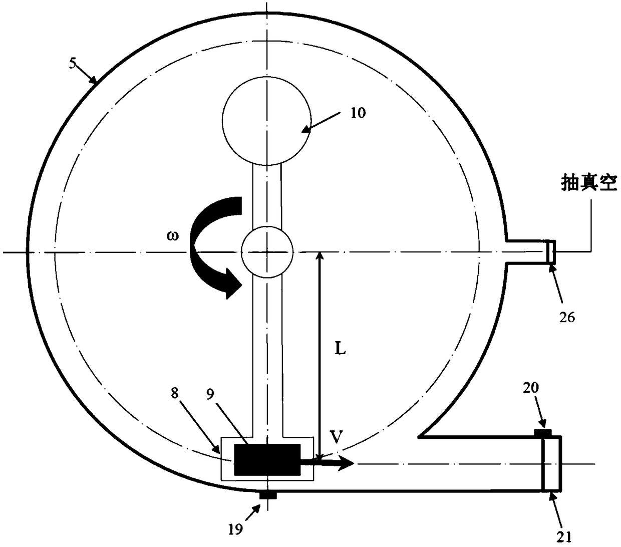
Centrifugal bird strike test method
A test method and centrifugal technology, which is applied in the field of bird strike test, can solve the problems of long-time charging and other problems, and achieve the effect of low noise, small space occupation and environmental friendliness
- Summary
- Abstract
- Description
- Claims
- Application Information
AI Technical Summary
Problems solved by technology
Method used
Image
Examples
Embodiment 1
[0049] Such as Figure 7 As shown, the test piece for the bird strike test is the propeller 22 of the aircraft, the motor 23 is connected with the propeller 22 through the transmission 24, and the transmission 24 is used to transmit the driving force generated by the motor 23 to the propeller 22 to drive the propeller 22 to rotate. The axis of 22 is parallel to the length direction of the guide tube 11 , and the propeller 22 is facing the guide tube 11 . The input shaft of the transmission 24 is connected with the motor shaft of the electric motor 23 through a coupling, and the output shaft of the transmission 24 is connected with the propeller 22 through another coupling. Preferably, the transmission 24 is a continuously variable transmission, and its structure is as well known to those skilled in the art, and will not be repeated here. The continuously variable transmission can continuously adjust the transmission ratio, so that the continuous adjustment of the rotation spe...
Embodiment 2
[0051] Such as Figure 7 As shown, the test piece for the bird strike test is the fan blade 22 of the aircraft, the motor 23 is connected with the fan blade 22 through a transmission 24, and the transmission 24 is used to transmit the driving force generated by the motor 23 to the fan blade 22 to drive the fan blade 22 When rotating, the axis of the fan blade 22 is parallel to the length direction of the guide pipe 11 , and the fan blade 22 faces the guide pipe 11 . The input shaft of the transmission 24 is connected with the motor shaft of the electric motor 23 through a coupling, and the output shaft of the transmission 24 is connected with the fan blade 22 through another coupling. Preferably, the transmission 24 is a continuously variable transmission, and its structure is as well known to those skilled in the art, and will not be repeated here. The continuously variable transmission can continuously adjust the transmission ratio, so that the continuous adjustment of the ...
PUM
 Abstract
Description
Claims
Application Information
 - R&D
- Intellectual Property
- Life Sciences
- Materials
- Tech Scout
- Unparalleled Data Quality
- Higher Quality Content
- 60% Fewer Hallucinations
Browse by: Latest US Patents, China's latest patents, Technical Efficacy Thesaurus, Application Domain, Technology Topic, Popular Technical Reports.
© 2025 PatSnap. All rights reserved.Legal|Privacy policy|Modern Slavery Act Transparency Statement|Sitemap|About US| Contact US: help@patsnap.com


