Optical transmitter-receiver with stable signal transmission

A signal transmission and optical transceiver technology, applied in the field of optical transceivers, can solve the problems of high price, temperature fluctuation of electronic components, and similar problems, and achieve the effects of improving heat dissipation, improving practicability, and improving stability

Inactive Publication Date: 2018-11-06
南安市柳信光电科技有限公司
View PDF0 Cites 4 Cited by
  • Summary
  • Abstract
  • Description
  • Claims
  • Application Information

AI Technical Summary

Problems solved by technology

[0002] The optical transceiver is the terminal equipment for optical signal transmission. Due to the improvement of the current technology and the reduction of the price of optical fiber, it has been well applied in various fields. Therefore, the manufacturers of various optical transceivers have sprung up, but most of the manufacturers here The technology is not fully mature, and the development of new technologies requires capital, manpower, and material resources. Most of these manufacturers are small and medium-sized enterprises, and various brands have appeared one after another, but the quality is still similar. Foreign optical transceivers are good but expensive. Therefore, domestic manufacturers The production of optical transceivers has been transformed to meet domestic needs
[0003] As a kind of communication equipment, the optical transceiver is widely used in people's life. When the optical transceiver is in use, the electronic components inside the optical transceiver will generate a lot of heat. The temperature change will easily lead to temperature drift of the electronic components, thereby reducing the The stability of the information transmission of the optical transceiver, not only that, the interface of the general optical transceiver is easy to loosen between the interface and the joint after a long period of use, which further reduces the stability of the signal transmission of the optical transceiver

Method used


Image

  • Optical transmitter-receiver with stable signal transmission
  • Optical transmitter-receiver with stable signal transmission
  • Optical transmitter-receiver with stable signal transmission

Examples


Embodiment Construction

[0027] The present invention is described in further detail now in conjunction with accompanying drawing. These drawings are all simplified schematic diagrams, which only illustrate the basic structure of the present invention in a schematic manner, so they only show the configurations related to the present invention.

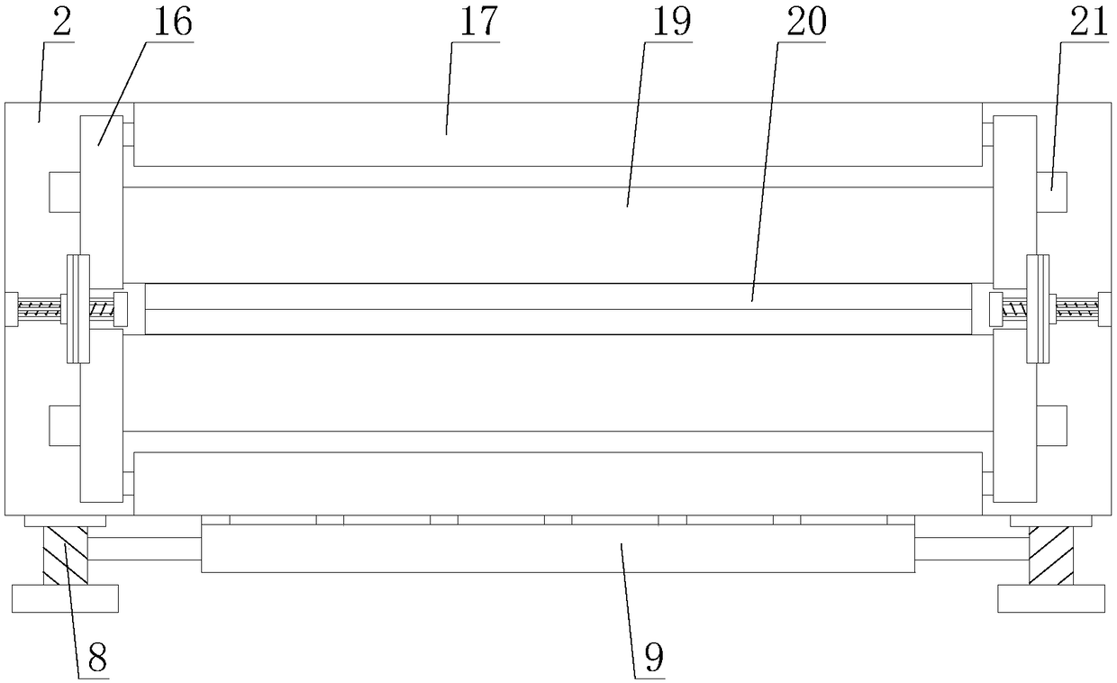
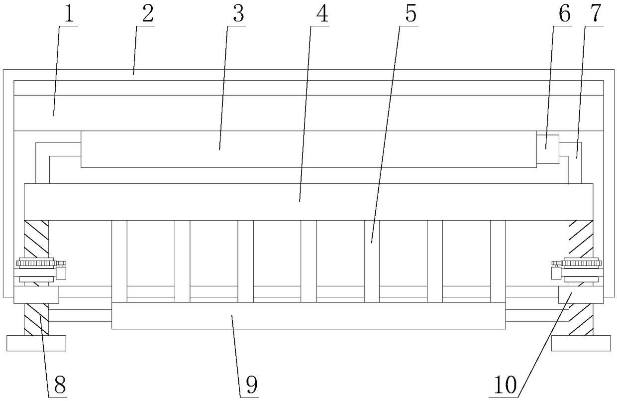
[0028] like figure 1 As shown, an optical transceiver with stable signal transmission includes a housing 2, a circuit board 1 and at least two interfaces 18, the circuit board 1 is horizontally arranged on the top of the interior of the housing 2, and each interface 18 is arranged on one side of the housing 2 The side also includes a heat dissipation mechanism and a reinforcement mechanism, the heat dissipation mechanism is arranged inside the casing 2, and the reinforcement mechanism is arranged on the side of the casing 2 close to the interface 18;

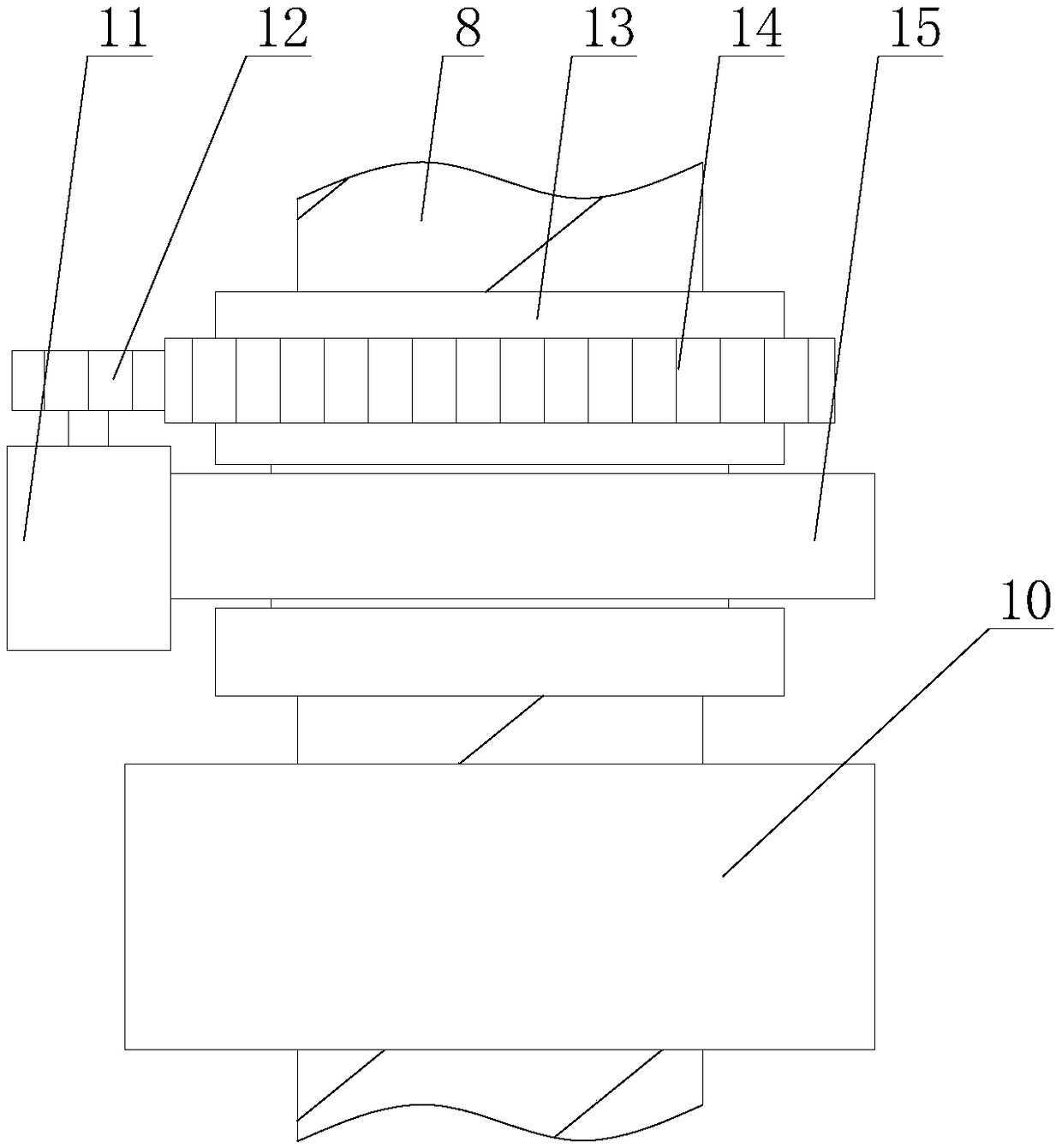
[0029] like figure 2 As shown, the heat dissipation mechanism includes a heat conducting plate 3, a water ...


PUM


Abstract

The invention relates to an optical transmitter-receiver with stable signal transmission. The optical transmitter-receiver comprises a shell, a circuit board and at least two interfaces, and further comprises a radiating mechanism and a reinforcing mechanism; the radiating mechanism comprises a heat-conducting plate, a water pump, a water tank, two water pipes, at least two radiating sheets, at least two reinforcing sleeves and at least two transceiving components; the reinforcing mechanism comprises two protective components and two locking components; the protective component comprises a connecting base, a cover plate, a rubber strip, two rotating rods and two limiting blocks; in the optical transmitter-receiver with stable signal transmission, the heat produced by the circuit is conducted to the external of the shell through the radiating mechanism, thereby reducing the influence on an electronic device on the circuit board by high temperature and improving the signal transmission stability of the optical transmitter-receiver; two rubber strips are driven to rotate through the reinforcing mechanism, so that the joint can be fixed through the rubber strip; the connection stability of the joint and the connector is improved, and the signal transmission stability of the optical transmitter-receiver is further improved.

Description

technical field [0001] The invention relates to the field of communication equipment, in particular to an optical transceiver with stable signal transmission. Background technique [0002] The optical transceiver is the terminal equipment for optical signal transmission. Due to the improvement of the current technology and the reduction of the price of optical fiber, it has been well applied in various fields. Therefore, the manufacturers of various optical transceivers have sprung up, but most of the manufacturers here The technology is not fully mature, and the development of new technologies requires capital, manpower, and material resources. Most of these manufacturers are small and medium-sized enterprises, and various brands have appeared one after another, but the quality is still similar. Foreign optical transceivers are good but expensive. Therefore, domestic manufacturers The production of optical transceivers has been transformed to meet domestic needs. [0003] ...

Claims


Application Information

Patent Timeline
Patent Type & Authority Applications(China)
IPC IPC(8): H04B10/40H05K7/20H05K5/02
CPCH04B10/40H05K5/02H05K7/20327H05K7/20436
Inventor 田波
Owner 南安市柳信光电科技有限公司
Why Eureka
Try Eureka