
Photovoltaic power generation device capable of efficiently cleaning in linkage way

A photovoltaic power generation and clean technology, applied in the field of solar cells, to achieve the effects of low contact resistance, low single-chip slurry requirement, and simple structure

Active Publication Date: 2018-11-06
赫冉新能源科技扬州有限公司
View PDF8 Cites 1 Cited by
  • Summary
  • Abstract
  • Description
  • Claims
  • Application Information

AI Technical Summary

Problems solved by technology

[0004] In order to solve the above technical problems, the present invention provides a high-efficiency linkage and cleaning photovoltaic power generation device to solve the problem of reliable cleaning of the surface of photovoltaic panels without dead ends, preventing dust accumulation on the surface of solar cells and affecting work efficiency, and reducing battery series resistance. Improve the photoelectric conversion efficiency and meet the requirements of environmental protection

Method used


Image

  • Photovoltaic power generation device capable of efficiently cleaning in linkage way
  • Photovoltaic power generation device capable of efficiently cleaning in linkage way
  • Photovoltaic power generation device capable of efficiently cleaning in linkage way

Examples


Embodiment 1

[0026] Embodiment 1 High-efficiency linked clean photovoltaic power generation device I

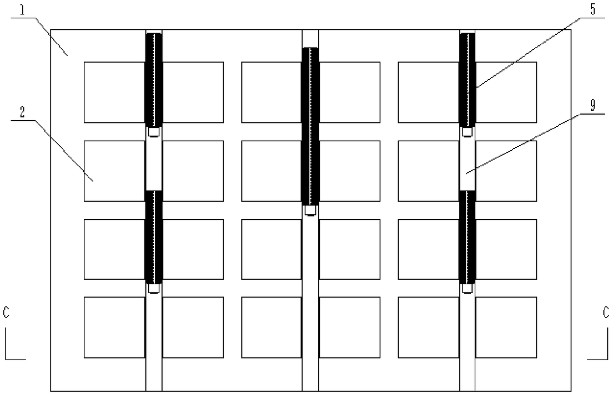
[0027] Figure 1-6 As shown, a high-efficiency linked and clean photovoltaic power generation device includes a mount 1 on which a plurality of solar cells 2 are installed. The electrode grid line, the silver electrode grid line is obtained by screen printing conductive silver paste I on the silicon wafer, then dried and sintered, and the center of the mounting base 1 is vertically pierced with a main rotating shaft 3, At least one auxiliary rotating shaft 4 is vertically arranged around the main rotating shaft 3, and a plurality of solar cells 2 are evenly distributed between the main rotating shaft 3 and the auxiliary rotating shaft 4, and the main rotating shaft 3 and the auxiliary rotating shaft The rotating shafts 4 are movably installed in the mounting base 1 respectively, and the upper ends of the main rotating shaft 3 and the secondary rotating shaft 4 protrude from the mounting ...

Embodiment 2

[0038] Example 2 High-efficiency linked clean photovoltaic power generation device II

[0039] Figure 1-6 As shown, a high-efficiency linked and clean photovoltaic power generation device includes a mount 1 on which a plurality of solar cells 2 are installed. The electrode grid line, the silver electrode grid line is obtained by screen printing conductive silver paste II on the silicon wafer, then dried and sintered, and the center of the mounting seat 1 is vertically pierced with a main rotating shaft 3, At least one auxiliary rotating shaft 4 is vertically arranged around the main rotating shaft 3, and a plurality of solar cells 2 are evenly distributed between the main rotating shaft 3 and the auxiliary rotating shaft 4, and the main rotating shaft 3 and the auxiliary rotating shaft The rotating shafts 4 are movably installed in the mounting base 1 respectively, and the upper ends of the main rotating shaft 3 and the secondary rotating shaft 4 protrude from the mounting b...

Embodiment 3

[0050] Example 3 High-efficiency linked clean photovoltaic power generation device III

[0051] Figure 1-6 As shown, a high-efficiency linked and clean photovoltaic power generation device includes a mount 1 on which a plurality of solar cells 2 are installed. The electrode grid line, the silver electrode grid line is obtained by screen printing conductive silver paste I on the silicon wafer, then dried and sintered, and the center of the mounting base 1 is vertically pierced with a main rotating shaft 3, At least one auxiliary rotating shaft 4 is vertically arranged around the main rotating shaft 3, and a plurality of solar cells 2 are evenly distributed between the main rotating shaft 3 and the auxiliary rotating shaft 4, and the main rotating shaft 3 and the auxiliary rotating shaft The rotating shafts 4 are movably installed in the mounting base 1 respectively, and the upper ends of the main rotating shaft 3 and the secondary rotating shaft 4 protrude from the mounting b...


PUM

PropertyMeasurementUnit
Particle sizeaaaaaaaaaa
Tap densityaaaaaaaaaa
Softening pointaaaaaaaaaa

Abstract

The invention discloses a photovoltaic power generation device capable of efficiently cleaning in a linkage way. The photovoltaic power generation device comprises an installation seat, wherein a plurality of solar cell pieces are arranged on the installation seat and comprises printed silver electrode grid lines, a main rotation shaft and at least one secondary rotation shaft are vertically arranged in the installation seat in a penetrating way, upper ends of the main rotation shaft and the secondary rotation shaft extend out of the installation seat and are respectively and horizontally connected with cleaning strip brushes, and lifting rotation adjustment assemblies are connected with lower ends of the main rotation shaft and the secondary rotation shaft. Compared with the prior art, the photovoltaic power generation device is compact in structure, lifting driving and rotation driving are efficiently combined, omnibearing cleaning on a surface of the solar cell panel and the storageof a cleaning tool can be stably and reliably achieved, the equipment complexity is reduced, cleaning brush heads on the cleaning strip brushes can rotate with the shafts to automatic finish the cleaning process, the cost is reduced, and the energy conversion efficiency is improved; and the solar cell piece is low in series resistance and high in photoelectric conversion efficiency, conforms to an environmental-protection concept and has a wide application prospect, and the new energy development demand is satisfied.

Description

technical field [0001] The invention relates to the technical field of solar cells, in particular to a high-efficiency linkage and clean photovoltaic power generation device. Background technique [0002] With the increasingly prominent problems of resource shortage and environmental pollution, solar energy, as a clean and renewable energy, has attracted more and more attention from the world. Therefore, the application of solar photovoltaic power generation is becoming more and more extensive. The key component of solar photovoltaic power generation technology is solar cells. In recent years, crystalline silicon solar cells have developed rapidly as the main solar photovoltaic power generation unit. Among them, the front side of solar cells is an important part of crystalline silicon solar cells. At present, commercial crystalline silicon solar cells The front electrode of the battery usually adopts printing and inkjet printing of conductive silver paste to form a grid lin...

Claims


Application Information

Patent Timeline
IPC IPC(8): H02S40/10H01B1/16H01B1/22H01B13/00
CPCH01B1/16H01B1/22H01B13/00H02S40/10Y02E10/50
Inventor 李超黄辉陈宝山夏平春徐芳唐军冯帅臣
Owner 赫冉新能源科技扬州有限公司
Learn More