
Hall device manufacturing method and Hall device

A technology of Hall device and metal electrode, applied in Hall device preparation, Hall device field, can solve the problem of low current carrying capacity and so on

Inactive Publication Date: 2018-11-06
NAT INST OF METROLOGY CHINA
View PDF7 Cites 4 Cited by
  • Summary
  • Abstract
  • Description
  • Claims
  • Application Information

AI Technical Summary

Problems solved by technology

[0003] Based on this, it is necessary to provide a Hall device with high current carrying capacity and electrode symmetry for the problem of low current carrying capacity of traditional Hall devices.

Method used


Image

  • Hall device manufacturing method and Hall device
  • Hall device manufacturing method and Hall device
  • Hall device manufacturing method and Hall device

Examples


Embodiment Construction

[0032] In order to make the purpose, technical solution and advantages of the present application clearer, the present application will be further described in detail through the following embodiments and in conjunction with the accompanying drawings. It should be understood that the specific embodiments described here are only used to explain the present application, not to limit the present application.

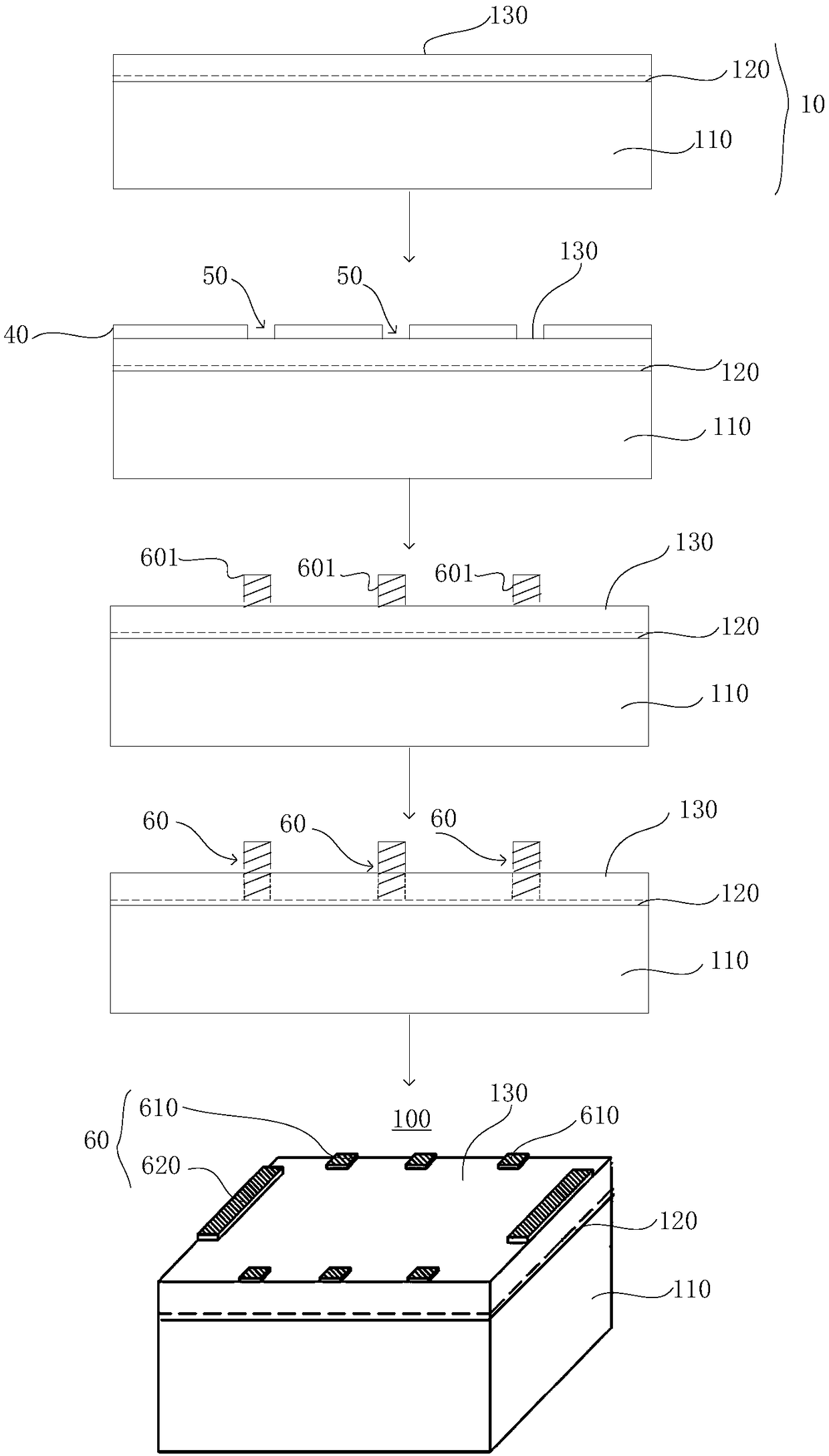
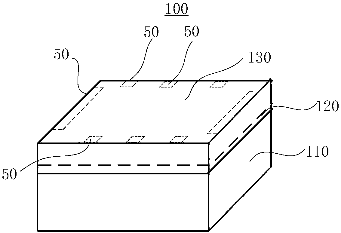
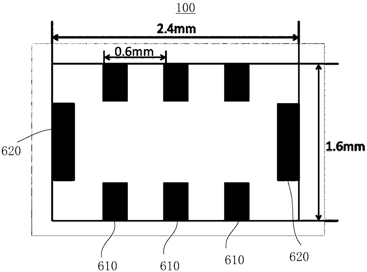
[0033] See Figure 1-2 , the application provides a method for preparing a Hall device comprising the following steps:

[0034] S10, providing a GaAs substrate 110;

[0035] S20, growing a two-dimensional electron gas structure layer 120 on the surface of the GaAs substrate 110 to form a GaAs substrate 10 having the two-dimensional electron gas structure layer 120, the GaAs substrate 10 having a GaAs substrate surface 130;

[0036] S30, providing a patterned mask layer 40, and using the mask layer 40 as a shield, forming a plurality of electrode windows 50 on the surface ...


PUM

PropertyMeasurementUnit
Thicknessaaaaaaaaaa

Abstract

A Hall device manufacturing method and a Hall device are provided. A Hall device obtained by a Hall device manufacturing method directly photoetches an electrode pattern on a GaAs substrate surface and deposits a metal layer so that a metal material contacts with a two-dimensional electron gas structure layer to form a plurality of metal electrodes. Then, GaAs substrate prepared with multiple metal electrodes is annealed in shielding gas to form good ohmic contact between GaAs substrate surface and two-dimensional electron gas structure layer. Finally, the Hall device is cut out along the outside of the plurality of metal electrodes by a scriber. There is no Hall rod structure in Hall devices, which makes Hall devices have relatively large critical current. At the same time, the patternedmask layer enables accurate symmetry of the plurality of metal electrodes to be ensured when photolithography is performed. Moreover, the success rate of the ohmic contact resistance between the GaAssubstrate surface and the two-dimensional electron gas structure layer is 100% due to the reduction of the process steps of chemical etching of the Hall rod in the Hall device fabrication process.

Description

technical field [0001] The present application relates to the field of quantum devices, in particular to a preparation method of a Hall device and a Hall device. Background technique [0002] The size of the components integrated on the current semiconductor chip is getting smaller and smaller, and the quantum effect becomes more and more non-negligible. At present, with the flattening of resistance measurement and the general trend of quantization reform of the SI unit system, the portable quantized resistance standard system based on quantum Hall devices has been widely used. In order to accurately measure the voltage of the Hall resistance, the current through the Hall device needs to be as large as possible without destroying the quantized state of the Hall device, and the device needs to have a higher current carrying capacity, that is, a higher critical current . The traditional Hall device has a Hall bar structure. The current is forced to flow down the length of th...

Claims


Application Information

Patent Timeline
IPC IPC(8): H01L43/04H01L43/06H01L43/14
CPCH10N52/80H10N52/01H10N52/101
Inventor 钟青王雪深李劲劲钟源
Owner NAT INST OF METROLOGY CHINA
Learn More