Down-the-hole holding-up hammer

A top hammer and down-the-hole technology, which is used in mining equipment and oil exploration fields, can solve the problems of reduced reliability, impact on performance and slag discharge effect, long exhaust gas path, etc., to ensure life and work reliability, Excellent slag discharge effect and long service life

Pending Publication Date: 2018-11-06
SHAREATE TOOLS
View PDF0 Cites 4 Cited by
  • Summary
  • Abstract
  • Description
  • Claims
  • Application Information

AI Technical Summary

Problems solved by technology

However, through in-depth customer understanding and research through international sales channels, as well as the collection of networked technical information and the analysis and comparison of manufacturer product sample structure diagrams, there are still problems in its structural design. The disadvantages include: (1) There are many internal parts and complex structures, such as Cylinder, outer sleeve and impact joint, which make the manufacturing cost too high and the reliability of use reduced; (2) The exhaust air path of the front and rear chambers of the piston is too long and the exhaust is insufficient, especially through the external spline side groove of the handle and the radial oblique There is a certain interference between the airflow direction of the center hole of the valve rod and the airflow direction of the center hole of the distribution rod, which affects the performance and slag discharge effect; (3) There are certain defects in the design of the piston structure, including the rationality of the weight of the piston, which makes the impact energy of the piston and the gear cone The structure of the drill bit does not match the working parameters, resulting in early failure of the internal bearing balls of the roller cone bit, early wear of the alloy teeth and other defects

Method used


Image

  • Down-the-hole holding-up hammer
  • Down-the-hole holding-up hammer
  • Down-the-hole holding-up hammer

Examples


Embodiment

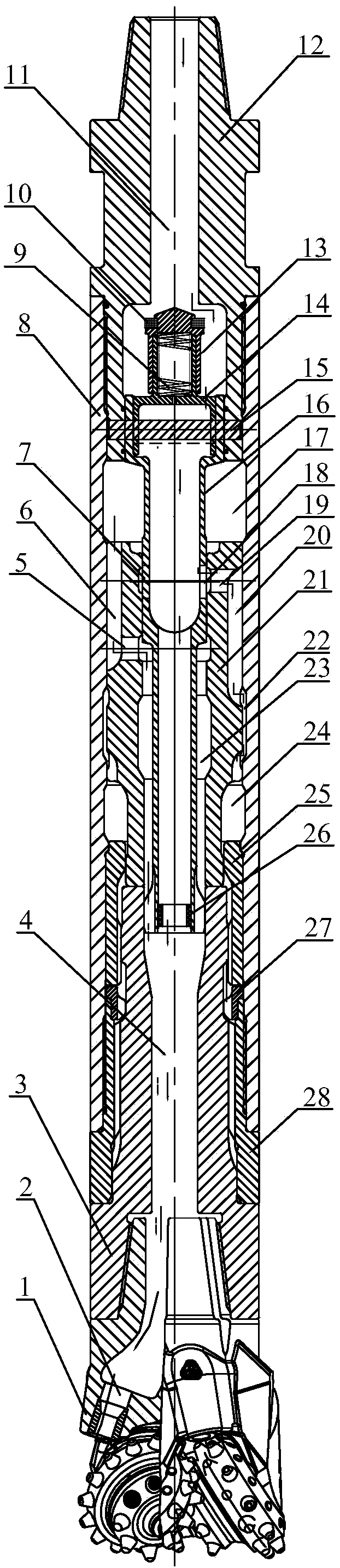
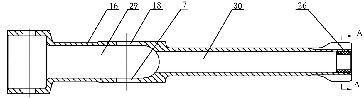
[0034] refer to Figure 1 to Figure 4 , a down-the-hole top hammer, comprising an outer casing 8, a check valve, a piston 21, a gas distribution rod 16, an impact joint 3, an upper joint 12, a lower joint 28, a guide sleeve 25, a retaining ring 27 and a roller cone bit 1; The upper and lower ends of the outer casing 8 are respectively fixedly socketed on the upper joint 12 and the lower joint 28, preferably, are respectively affixed to the upper and lower ends of the outer sleeve 8 through threaded upper and lower joints; the upper and lower joints are all hollow shape, wherein the central hole of the upper joint 12 is the air inlet; the roller cone bit 1 is installed on the lower joint 28 of the lower end of the outer sleeve 8 through the impact joint 3, and the roller cone bit 1 is fixedly connected with the impact joint 3 , preferably, the impact joint 3 with the API internal taper thread is fixedly connected with the drill pipe of the roller cone bit 1 with the API externa...


PUM


Abstract

A down-the-hole holding-up hammer comprises an outer casing pipe, a piston, an air distribution rod, an impact joint and a roller bit. An air inlet is formed in the upper end of the outer casing pipe,the lower end of the outer casing pipe is connected with the roller bit through the impact joint, and the impact joint is provided with a joint ventilating hole communicating with an inner hole spraying nozzle of the roller bit; the air distribution rod is fixedly arranged in the outer casing pipe, and the upper end outer wall of the air distribution rod and the inner wall of the outer casing pipe are fixed in a contact mode; the lower end of the air distribution rod extends into the joint ventilating hole in the impact joint, and the lower end outer wall of the air distribution rod is in contact fit with the inner wall of the joint ventilating hole in the impact joint; and the piston is arranged between the outer casing pipe and the air distribution rod, the piston can do up-down reciprocating impact movement in the axial direction of the outer casing pipe, and the bottom end face of the piston serves as an impact acting face acting on the impact joint. According to the down-the-holeholding-up hammer, the higher perforation efficiency and long service life are achieved under the pressure of 6-7.5 bar.

Description

technical field [0001] The invention relates to the field of oil exploration and mining equipment, in particular to a down-the-hole top hammer, which is suitable for blast holes in various types of mining. Background technique [0002] The down-the-hole top hammer is based on the rock-breaking mechanism of the roller cone bit, which is mainly spinning and scraping, and uses the piston driven by wind pressure to give a reasonable reciprocating impact on the rear end face of the roller cone bit to change and enhance its rock-breaking effect. A brand new rock-breaking mechanism. It is connected through the impact joint of the down-the-hole top hammer, which converts the impact energy of the piston into the form of stress wave and effectively transmits it to each cutting alloy tooth distributed by the roller cone bit, so that the rock drilling perforation efficiency of the roller cone bit is improved. An advanced optimization combination technology greatly improved. [0003] T...

Claims


Application Information

Patent Timeline
Patent Type & Authority Applications(China)
IPC IPC(8): E21B4/14
CPCE21B4/14
Inventor 赵鹏建王磊朱策刘勇
Owner SHAREATE TOOLS
Why Eureka
Try Eureka