Chamfering grinding device used for motor stator and operation method of chamfering grinding device

A motor stator and chamfering technology, which is used in grinding/polishing equipment, machine tools suitable for grinding workpiece edges, metal processing equipment, etc. Small problems such as avoiding shaking, improving chamfering efficiency and reducing labor intensity

Pending Publication Date: 2018-11-06
NANLING LIANG POWER TOOLS
View PDF7 Cites 0 Cited by
  • Summary
  • Abstract
  • Description
  • Claims
  • Application Information

AI Technical Summary

Problems solved by technology

[0003] The purpose of the present invention is to overcome the problems of the existing motor stator chamfering grinding equipment, such as low quality of stator chamfering, small scope of application, and low stability of the stator during chamfering, and to provide a machine with reasonable structure design, convenient operation, Chamfering and grinding equipment for motor stators with good chamfering quality, good stator stability during chamfering, and low labor intensity for operators and its operating method

Method used


Image

  • Chamfering grinding device used for motor stator and operation method of chamfering grinding device
  • Chamfering grinding device used for motor stator and operation method of chamfering grinding device
  • Chamfering grinding device used for motor stator and operation method of chamfering grinding device

Examples


Embodiment 1

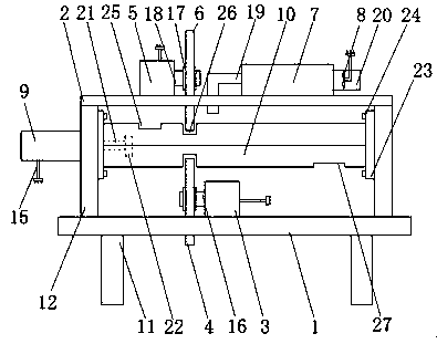
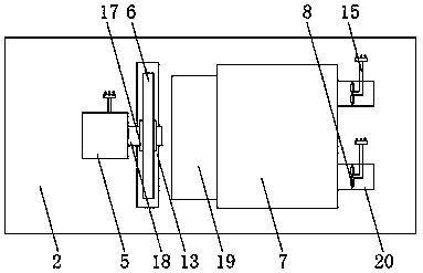
[0025] as attached Figure 1-4 As shown, a chamfering and grinding equipment for motor stators includes a bottom plate 1, a top plate 2, a motor one 3, a chamfering wheel one 4, a motor two 5, a chamfering wheel two 6, a chip collection box 7, a fan 8, The cylinder 9 and the limiting plate 10 are characterized in that: the base plate 1 is arranged on the support 11, the base plate 1 is provided with a vertical plate 12, a fixing groove 13, and a limiting groove 14 is arranged on the vertical plate 12, so The top plate 2 is set on the vertical plate 12, the motor one 3 is set on the bottom, and the motor one 3 is provided with a power line 15 and a transmission shaft one 16, and the bottom of the chamfering wheel one 4 passes through Fixing groove 13 on the bottom, and chamfering wheel one 4 is arranged on transmission shaft one 16 by mounting ring 17, described motor two 5 is arranged on the top plate 2, and is provided with power line 15, on motor two 5, Transmission shaft t...

Embodiment 2

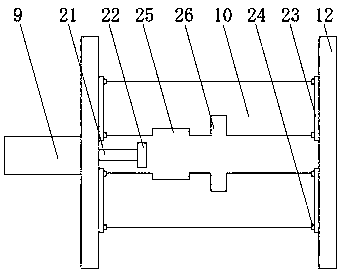
[0037] as attached Figure 5 As shown, a chamfering and grinding equipment for motor stators includes a bottom plate 1, a top plate 2, a motor one 3, a chamfering wheel one 4, a motor two 5, a chamfering wheel two 6, a chip collection box 7, a fan 8, The cylinder 9 and the limiting plate 10 are characterized in that: the base plate 1 is arranged on the support 11, the base plate 1 is provided with a vertical plate 12, a fixing groove 13, and a limiting groove 14 is arranged on the vertical plate 12, so The top plate 2 is set on the vertical plate 12, the motor one 3 is set on the bottom, and the motor one 3 is provided with a power line 15 and a transmission shaft one 16, and the bottom of the chamfering wheel one 4 passes through Fixing groove 13 on the bottom, and chamfering wheel one 4 is arranged on transmission shaft one 16 by mounting ring 17, described motor two 5 is arranged on the top plate 2, and is provided with power line 15, on motor two 5, Transmission shaft two...


PUM


Abstract

The invention discloses a chamfering grinding device used for a motor stator. The chamfering grinding device used for the motor stator comprises a bottom plate, a top plate, a first motor, a first chamfering wheel, a second motor, a second chamfering wheel, a chip collecting box, a fan, a cylinder and limiting plates, and is characterized in that the bottom plate is arranged on a support; the topplate is arranged on a vertical plate; the first motor is arranged on the bottom plate; the bottom of the first chamfering wheel penetrates through a fixed groove in the bottom plate; the second motoris arranged on the top plate; the bottom of the second chamfering wheel penetrates through a fixed groove in the top plate; and the chip collecting box is arranged on the top plate. According to thechamfering grinding device used for the motor stator, a piston rod on the cylinder is provided with a pushing plate, the cylinder pushes the piston rod to move, the piston rod pushes the pushing plate, so that the pushing plate pushes the motor stator to move between the limiting plates; the bottom end and the top end of the motor stator in the moving process make contact with the first chamferingwheel and the second chamfering wheel in the rotating process correspondingly; and chamfering is performed at the bottom end and the top end of the motor stator at the same time, and the chamfering quality of the motor stator is improved.

Description

technical field [0001] The invention relates to chamfering and grinding equipment, in particular to a chamfering and grinding equipment for motor stators and an operating method thereof. Background technique [0002] At present, the stators of servo motors are mostly made of buckled or self-fastened stator pieces. In order to improve the connection strength of two adjacent stator pieces, the stator is often chamfered. For example, the patent application number 201220145726. The stator inner and outer magnetic pole hole chamfering machine solves the problem of low efficiency of motor chamfering, but it has the problems of low quality of stator chamfering, small application range, and low stability of the stator during chamfering. Contents of the invention [0003] The purpose of the present invention is to overcome the problems of the existing motor stator chamfering grinding equipment, such as low quality of stator chamfering, small scope of application, and low stability ...

Claims


Application Information

Patent Timeline
Patent Type & Authority Applications(China)
IPC IPC(8): B24B27/00B24B9/04B24B55/06B24B55/12B24B1/00H02K15/02
CPCH02K15/02B24B1/00B24B9/04B24B27/0076B24B27/0092B24B55/06B24B55/12
Inventor 徐红耀王建良
Owner NANLING LIANG POWER TOOLS
Why Eureka
Try Eureka