
Electronic device

A technology for electronic devices and electronic components, which is applied in the directions of circuits, electrical components, and electrical solid-state devices, and can solve problems such as the increased warpage of the substrate.

Active Publication Date: 2018-11-02
SHINDENGEN ELECTRIC MFG CO LTD
View PDF4 Cites 0 Cited by
  • Summary
  • Abstract
  • Description
  • Claims
  • Application Information

AI Technical Summary

Problems solved by technology

In such a semiconductor device, if the region where the conductor layer is not arranged on the substrate becomes longer, the warpage of the substrate may increase.

Method used


Image

  • Electronic device
  • Electronic device
  • Electronic device

Examples


no. 1 approach

[0038] "constitute"

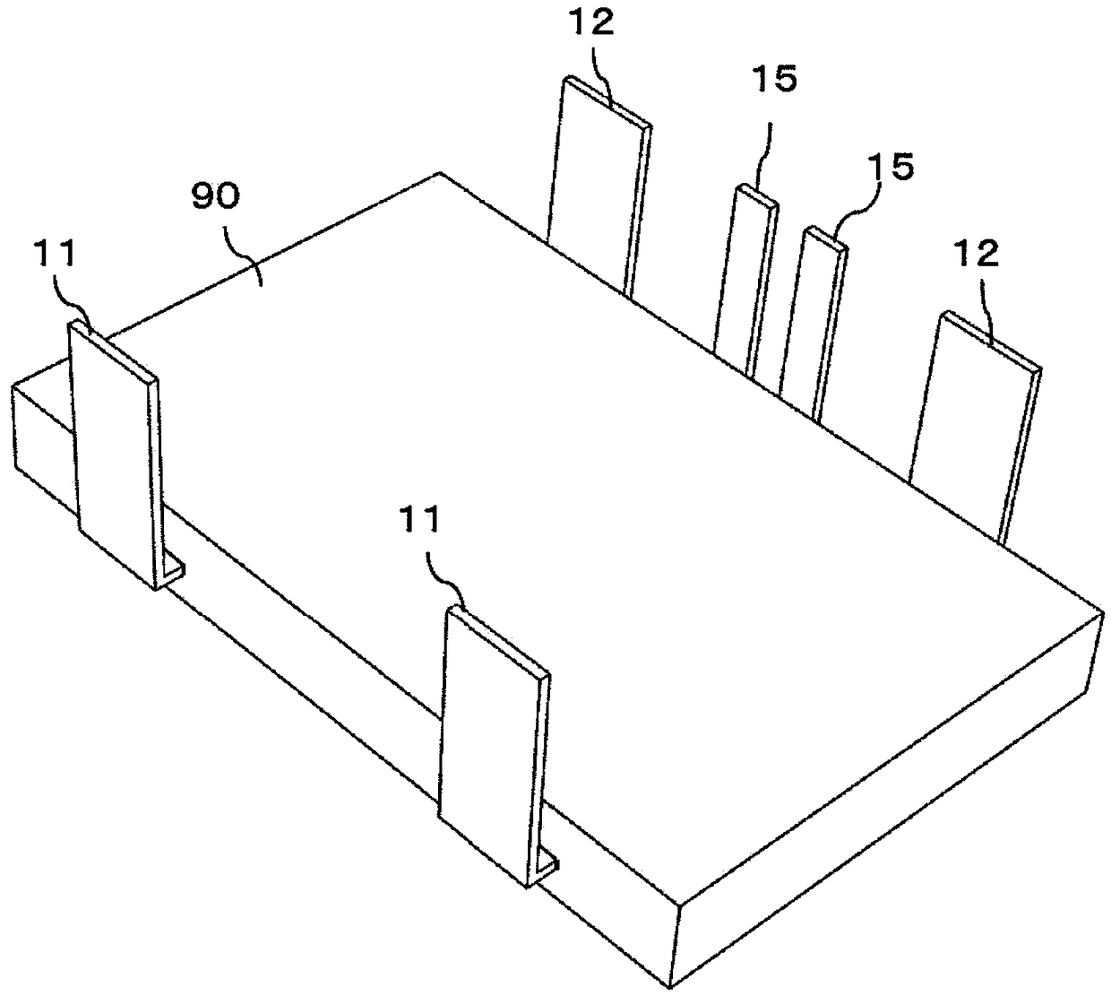
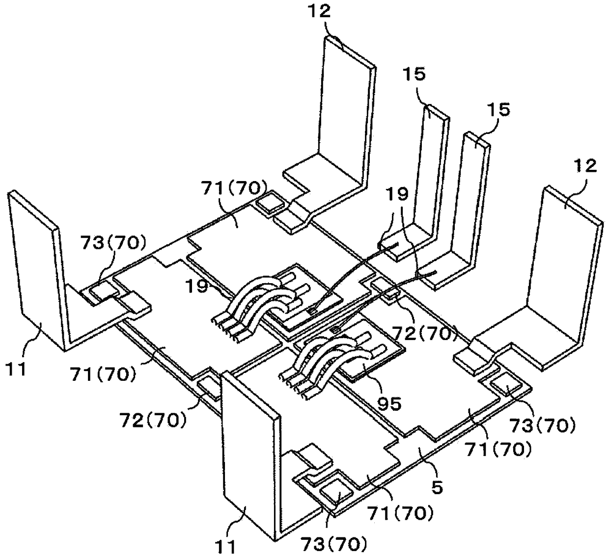
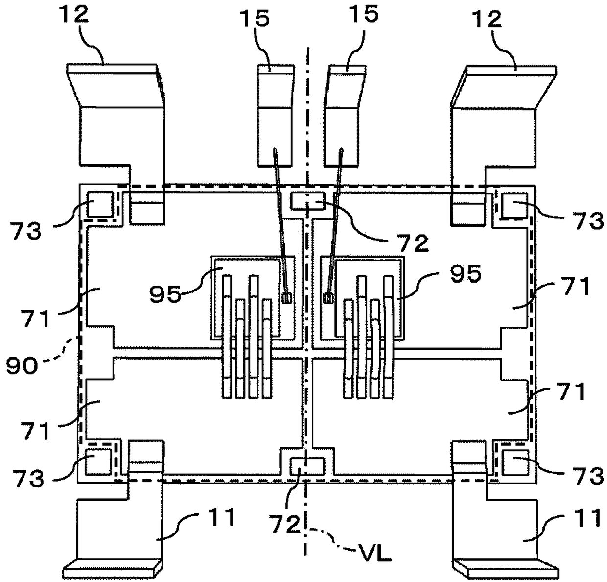
[0039] Such as figure 2 As shown, a semiconductor device as an example of an electronic device according to this embodiment may include a sealing portion 90 made of a sealing resin (refer to figure 1 ); the first main terminal 11 protruding outward from the first side surface of the package portion 90 ; and the semiconductor element 95 as an example of an electronic component arranged in the package portion 90 .

[0040] In this embodiment, a semiconductor device is used as an electronic device and a semiconductor element 95 is used as an electronic element for description, but the present invention is not limited thereto, and in particular, it is not necessarily limited to "semiconductor".

[0041] The semiconductor device of the present embodiment further includes second main terminals 12 through which main current flows while protruding from package portion 90 to the outside. figure 2 The front side of the semiconductor element 95 shown in is elect...


PUM


Abstract

This electronic device is provided with: a substrate 5; a plurality of first conductor layers 71 provided on the substrate 5; second conductor layers 72 provided on the substrate 5; electronic elements 95 provided to the first conductor layers 71; and a sealing part 90 which covers the substrate 5, the first conductor layers 71, the second conductor layers 72, and the electronic elements 95. The first conductor layers 71 are not provided on a virtual line VL which includes the second conductor layers 72, and which extends in an in-plane direction of the substrate 5. The second conductor layers72 are sealed inside the sealing part 90, and are only covered by the sealing part 90.

Description

technical field [0001] The present invention relates to electronic devices. Background technique [0002] Conventionally, a semiconductor element as an electronic element is placed on a conductive layer of a substrate, and the surface of the semiconductor element and the terminal are connected with a bonding wire or a connector by solder or the like, and the conductive layer, semiconductor element, bonding wire, etc. Such an electronic device is widely known as an example of a semiconductor device in which a package such as a connector and the like is packaged with a package such as a package resin (see Japanese Patent Application Laid-Open No. 2014-195064). In such a semiconductor device, if the region where the conductor layer is not disposed on the substrate becomes longer, the warpage of the substrate may increase. [0003] In view of the above problems, an object of the present invention is to provide an electronic device capable of preventing the warpage of the substr...

Claims


Application Information

Patent Timeline
Patent Type & Authority Applications(China)
IPC IPC(8): H01L23/12H05K1/02
CPCH05K1/02H01L2224/0603H01L2224/48247H01L2224/4903H01L2224/49431H01L23/3107H01L23/562H01L25/072H01L2224/49111H01L24/49H01L2224/04042H01L2924/3511H01L2224/48227H01L2224/73265H01L2224/26175H01L2224/291H01L24/48H01L2224/48091H01L24/32H01L24/29H01L2224/32225H01L2924/00012H01L2924/014H01L2924/00014H01L23/12H01L23/28H01L25/07H01L25/18H01L23/3121
Inventor 梅田宗一郎森永雄司
Owner SHINDENGEN ELECTRIC MFG CO LTD
Learn More