Injection molding flash detection device

A detection device and flash technology, which is applied in the field of plastic parts processing, can solve the problems of low flash processing efficiency, and achieve the effects of avoiding continuous work, improving processing efficiency, and reducing grinding work

Active Publication Date: 2018-11-02
重庆雷钜电子科技有限公司
View PDF5 Cites 1 Cited by
  • Summary
  • Abstract
  • Description
  • Claims
  • Application Information

AI Technical Summary

Problems solved by technology

[0004] The present invention intends to provide an injection molding flash detection device to solve the problem of low processing efficiency of flash of plastic fittings in the prior art

Method used


Image

  • Injection molding flash detection device
  • Injection molding flash detection device

Examples


Embodiment Construction

[0024] The following is further described in detail through specific implementation methods:

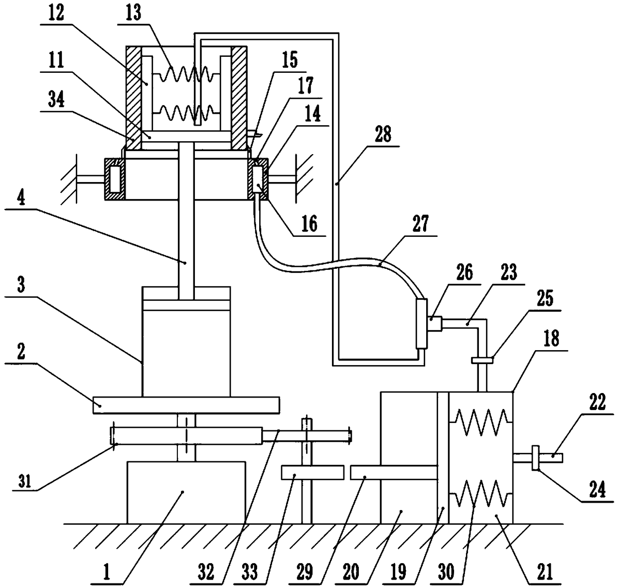
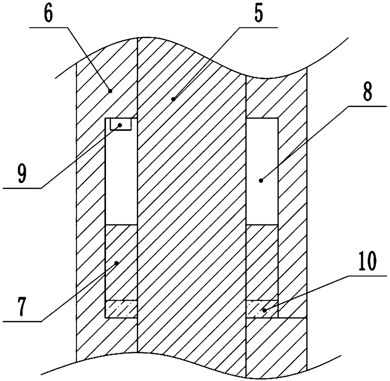
[0025] The reference signs in the drawings of the description include: motor 1, rotating plate 2, cylinder 3, vertical shaft 4, inner shaft 5, outer shaft 6, slider 7, chute 8, switch 9, sponge layer 10, horizontal plate 11 , clamping piece 12, first spring 13, detection ring 14, cutter 15, annular cavity 16, air outlet hole 17, cylinder body 18, piston 19, left chamber 20, right chamber 21, air inlet pipe 22, outlet Air pipe 23, first one-way valve 24, second one-way valve 25, vortex tube 26, first air pipe 27, second air pipe 28, piston rod 29, second spring 30, first gear 31, second gear 32, cam 33, plastic pipe fitting 34.

[0026] The embodiment is basically as figure 1 As shown, the injection molding flash detection device includes a frame, and a motor 1 is installed on the frame. The output end of the motor 1 is fixedly connected to the rotating plate 2. The rotating plate 2...


PUM


Abstract

The invention relates to the technical field of plastic part processing, and particularly discloses an injection molding flash detection device. The injection molding flash detection device comprisesa rack. A motor is installed on the rack. An output end of the motor is fixedly connected with a rotary plate. An air cylinder is installed on the rotary plate. An output end of the air cylinder is coaxially and fixedly connected with a vertical shaft. The vertical shaft comprises an inner shaft body and an outer shaft body. A sliding groove is formed in the inner wall of the outer shaft body. A switch for controlling the motor to work is installed on the top wall of the sliding groove. A sliding block is fixedly connected with the outer wall of the inner shaft body. The sliding block is in sliding connection with the sliding groove. The top end of the inner shaft body is connected with a clamping mechanism used for clamping an injection molding part. A detection ring is arranged between the air cylinder and a transverse plate. The detection ring is fixedly connected to the rack. The detection ring and the injection molding part are arranged coaxially. The inner diameter of the detection ring is larger than the outer diameter of the injection molding part. A tool for cutting off flash is fixedly connected with the side, facing the transverse plate, of the detection ring. The tool is arranged to be attached to the outer wall of the injection molding part. The injection molding flash detection device can achieve detection on the flash of an injection molding part, and can automatically deal with the flash after detecting that flash exists on the injection molding part.

Description

technical field [0001] The invention relates to the technical field of plastic parts processing, and specifically discloses an injection molding flash detection device. Background technique [0002] Flash, also known as overflow, burr, burr, etc., mostly occurs at the parting and closing positions of the mold, such as the parting surface of the moving mold and the fixed mold, etc. The flash is largely due to the mold or machine lock. Caused by mold force failure. Generally speaking, due to the influence of various factors, plastic parts will basically produce flash. Therefore, in the subsequent processing of plastic parts, the flash must be removed to ensure the quality and appearance of plastic parts. [0003] The Chinese invention patent with the application number of 201711346629.1 discloses a fully automatic trimming device for plastic trimming of chair plastic parts. The mechanism includes a rotating disk, half of the edge of the rotating disk is provided with a grin...

Claims


Application Information

Patent Timeline
Patent Type & Authority Applications(China)
IPC IPC(8): B29C45/00B29C37/02
CPCB29C45/0053B29C2045/0077
Inventor 戴江毅
Owner 重庆雷钜电子科技有限公司
Why Eureka
Try Eureka