
A high-safety wire stranding machine

A safe, twisting machine technology, applied in the manufacture of circuits, electrical components, cables/conductors, etc., can solve problems such as low efficiency, easy residual impurities, and influence of wire energization efficiency, and achieve high stranding efficiency and easy cleaning of impurities , Improve the effect of stranding efficiency

Active Publication Date: 2019-12-13
ELECTRIC POWER RES INST OF GUANGDONG POWER GRID
View PDF7 Cites 0 Cited by
  • Summary
  • Abstract
  • Description
  • Claims
  • Application Information

AI Technical Summary

Problems solved by technology

[0005] In order to overcome the shortcomings of the current manual twisting method, which is low in efficiency and tends to leave a lot of impurities, which affects the power-on efficiency of the wire in the later stage, the technical problem to be solved by the invention is to provide a twisted wire with high efficiency and convenient High-safety wire stranding machine for cleaning impurities

Method used


Image

  • A high-safety wire stranding machine
  • A high-safety wire stranding machine
  • A high-safety wire stranding machine

Examples


Embodiment

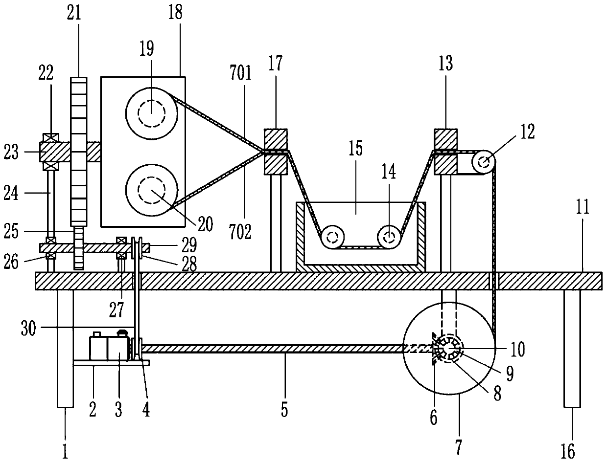
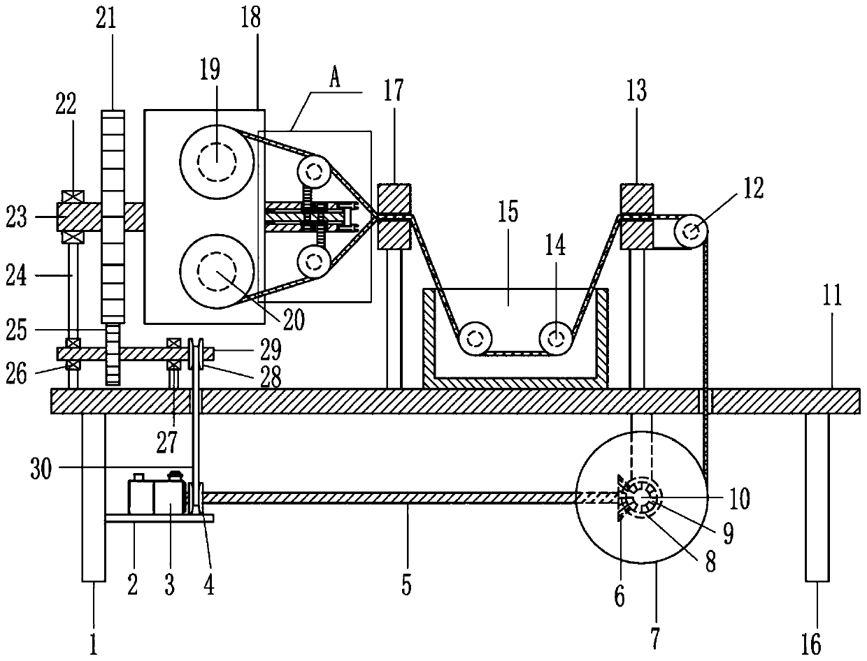
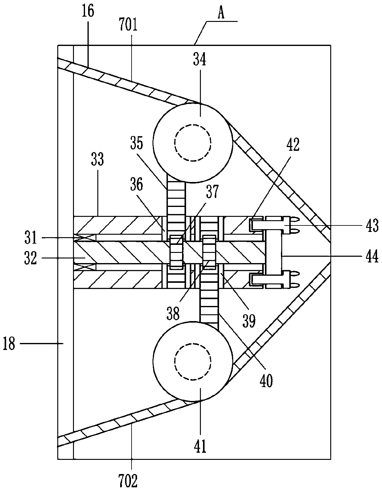
[0030] A high-safety wire twisting machine such as Figure 1-8As shown, it includes a first pillar 1, a first fixed plate 2, a driving motor 3, a first transmission wheel 4, a first rotating shaft 5, a first bevel gear 6, a first bobbin 7, a first bearing seat 8, The second bevel gear 9, the second rotating shaft 10, the table board 11, the first guide wheel 12, the wiping block 13, the second guide wheel 14, the cleaning tank 15, the second pillar 16, the guide frame 17, the mounting plate 18, the second Bobbin 19, third bobbin 20, first circular gear 21, second bearing seat 22, third rotating shaft 23, second fixing plate 24, second circular gear 25, third bearing seat 26, fourth bearing Seat 27, second drive wheel 28, fourth rotating shaft 29, drive belt 30, first electric wire 701 and second electric wire 702; 11 The other side of the bottom; the first fixed plate 2 is fixed on the side of the first pillar 1 close to the second pillar 16, and the drive motor 3 is fixed on...


PUM


Abstract

The present invention relates to the field of wire manufacturing, and specifically to a high-security wire stranding machine. The technical problem to be solved by the present invention is to providea high-security wire stranding machine with high stranding efficiency and easy cleaning of impurities. The high-security wire stranding machine comprises a first pillar, a first fixed plate, a drivingmotor, a first transmission wheel, a first rotating shaft, a first bevel gear, a first bobbin, a first bearing seat, a second bevel gear, a second rotating shaft, a table plate, a first guide wheel,a wiping block, a second guiding wheel, a cleaning tank, a second pillar, a guide frame, a mounting plate, a second bobbin, a third bobbin, a circular gear, a second bearing seat, a third rotating shaft, a second fixed plate, a second circular gear, a third bearing seat, a fourth bearing seat, a second transmission wheel, a fourth rotating shaft, a transmission belt and the like. The high-securitywire stranding machine in the invention achieves the effects of high stranding efficiency and easy cleaning of impurities.

Description

technical field [0001] The invention relates to the field of electric wire manufacturing, in particular to a high-safety electric wire stranding machine. Background technique [0002] Generally, the wire is composed of an insulating layer and a plurality of thin conductive cores covered. When wiring, it is usually necessary to strip off the insulating layer of the terminal and then twist the inner thin conductive cores together to facilitate the wiring requirements; Therefore, the stranded wire is formed by helically twisting the thin conductive core wires according to certain rules. [0003] At present, the stranding method is mainly manual operation, the processing method is backward, and the efficiency is low, which obviously does not meet the needs of production and processing, and through manual operation, it is easy to leave a lot of impurities, which will affect the power-on efficiency of the wire in the later stage. [0004] To sum up, there is a need to develop a h...

Claims


Application Information

Patent Timeline
Patent Type & Authority Patents(China)
IPC IPC(8): H01B13/00H01B13/02H01B13/30
CPCH01B13/0036H01B13/0207H01B13/0292H01B13/30
Inventor 张洪运
Owner ELECTRIC POWER RES INST OF GUANGDONG POWER GRID
Learn More