


Quick Research
Generate reliable direction feasibility study reports for your R&D in just a few steps.

Technical Q&A
Discover and master advanced knowledge NOW. Basics, ideas, possibilities, all at once.

Find Solutions
As an expert in R&D theories, this can generate solutions to your technical problems instantly.

Evaluate Feasibility
Analyze your overall solution with one click, know your potential R&D risks in advance.

Monitor Landscape
Get weekly tech updates, stay abreast of the latest tech innovations and key insights.
Controlling method and controlling device of vehicle emission controlling system and controlling system
A technology of an emission control system and a control method, which is applied in the directions of exhaust devices, electrical control, and mufflers, etc., can solve problems such as excessive emission, over-injection of urea, under-injection of reducing agent, etc.
- Summary
- Abstract
- Description
- Claims
- Application Information
AI Technical Summary
Problems solved by technology
Method used
Image


Examples
Embodiment 1
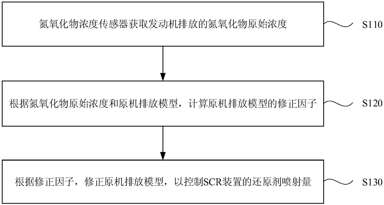
[0026] figure 1 It is a flow chart of a control method for a vehicle emission control system provided in Embodiment 1 of the present invention. The vehicle emission control system includes an engine and an electronic control unit. The engine includes a nitrogen oxide concentration sensor and a selective catalytic reduction SCR device. The original engine emission model is stored in the control unit, and the original engine emission model includes the corresponding relationship between the nitrogen oxide concentration and the reducing agent injection amount of the SCR device; the control method includes:
[0027] Step 110, the nitrogen oxide concentration sensor acquires the original concentration of nitrogen oxides emitted by the engine.
[0028] It is understood that under the conditions of high pressure and temperature inside the engine, nitrogen (N 2 ) and oxygen (O 2 ) react to form a variety of nitrogen and oxygen compounds collectively known as nitrogen oxides (NOx). ...
Embodiment 2
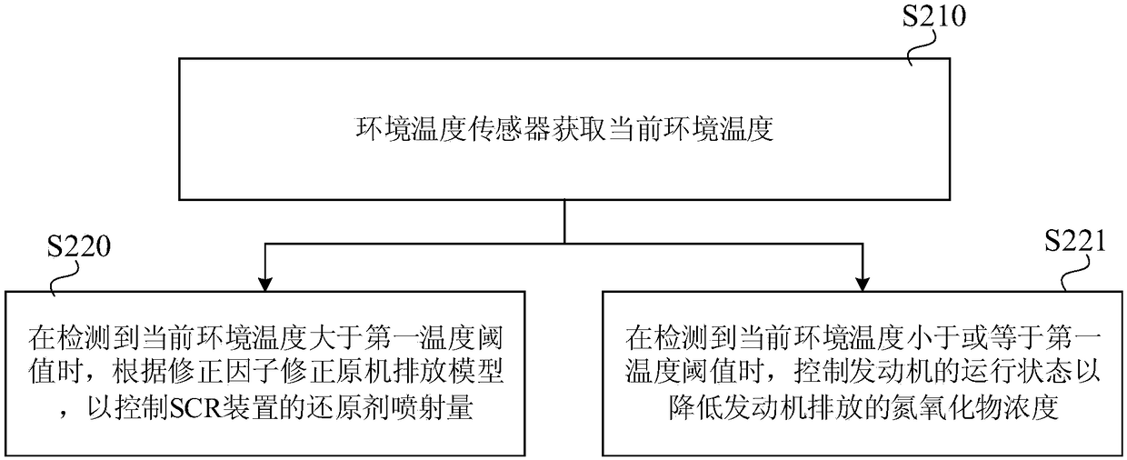
[0035] figure 2 It is a flow chart of a control method of a vehicle emission control system provided by Embodiment 2 of the present invention. This embodiment is based on the above embodiments. Optionally, the engine engine of the vehicle control system further includes an ambient temperature sensor, The control method also includes:
[0036] Step 210, the environment temperature sensor acquires the current environment temperature.
[0037] Wherein, the ambient temperature sensor may be arranged outside the engine, such as a thermal resistance type or a thermocouple type temperature sensor, for detecting the current ambient temperature, which is not limited in this embodiment of the present invention.
[0038] Step 220 , when it is detected that the current ambient temperature is greater than the first temperature threshold, correct the original engine emission model according to the correction factor, so as to control the reductant injection amount of the SCR device.
[00...
Embodiment 3
[0064] Figure 4 It is a schematic structural diagram of a vehicle emission control device provided in Embodiment 3 of the present invention. The control device provided in this embodiment is used in a vehicle emission control system. The vehicle emission control system includes an engine 100 and an electronic control unit 200. The engine 100 includes a nitrogen oxide concentration sensor 101 and an SCR device 102, and the electronic control unit 200 stores an original machine emission model, which includes the corresponding relationship between the nitrogen oxide concentration and the reducing agent injection amount of the SCR device 102; refer to Figure 4 , the vehicle emission control device includes:
[0065] The obtaining module 10 is used to obtain the original concentration of nitrogen oxides emitted by the engine obtained by the nitrogen oxide concentration sensor; the calculation module 20 is used to calculate the correction factor of the original machine emission mo...
PUM
 Abstract
Description
Claims
Application Information
 - R&D Engineer
- R&D Manager
- IP Professional
- Industry Leading Data Capabilities
- Powerful AI technology
- Patent DNA Extraction
Browse by: Latest US Patents, China's latest patents, Technical Efficacy Thesaurus, Application Domain, Technology Topic, Popular Technical Reports.
© 2024 PatSnap. All rights reserved.Legal|Privacy policy|Modern Slavery Act Transparency Statement|Sitemap|About US| Contact US: help@patsnap.com