Network transformer automatic detection device

An automatic detection and network transformer technology, applied in the field of network transformers, can solve the problems of low quality inspection efficiency of network transformer pins, and achieve the effect of avoiding interference

Inactive Publication Date: 2018-10-23
ZHONGJIANG KAIXUN ELECTRONICS
View PDF0 Cites 0 Cited by
  • Summary
  • Abstract
  • Description
  • Claims
  • Application Information

AI Technical Summary

Problems solved by technology

[0004] The purpose of the present invention is to provide an automatic detection device for network transformers, to solve the problem of low quality inspection efficiency of network transformer pins in the prior art, and to achieve the purpose of improving the quality inspection efficiency of network transformers through photoelectric methods

Method used


Image

  • Network transformer automatic detection device
  • Network transformer automatic detection device
  • Network transformer automatic detection device

Examples


Embodiment 1

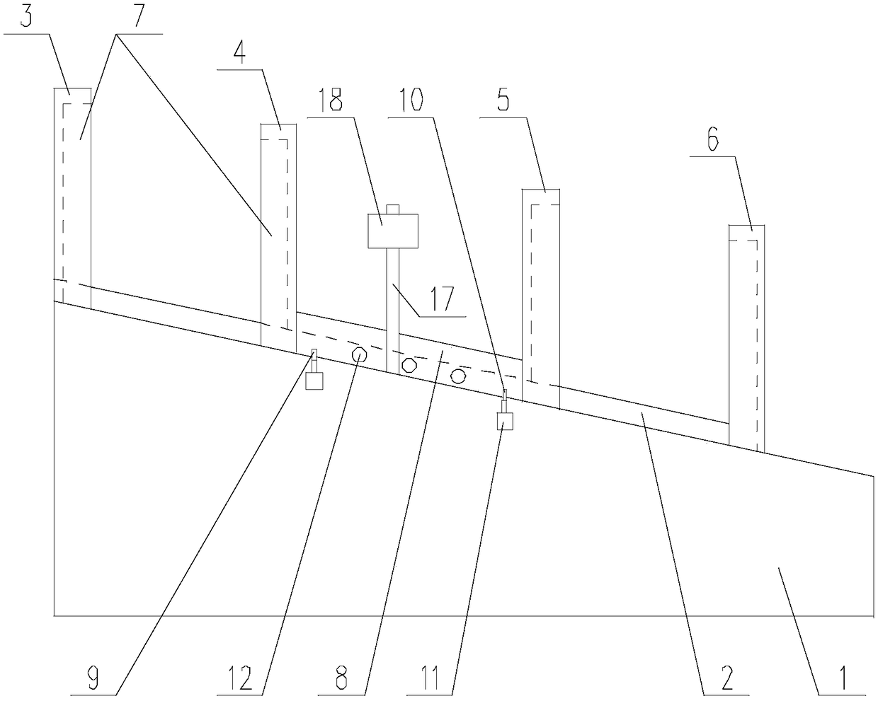
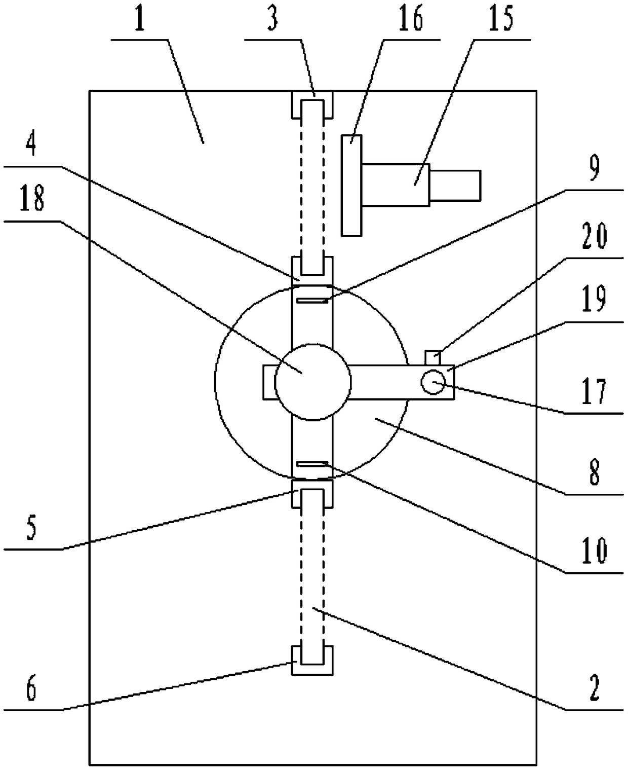
[0028] Such as Figure 1 to Figure 6 The shown network transformer automatic detection device includes a platform body 1, an inclined track 2 is set on the platform body 1, and a first square column 3, a second square column 4, The third party column 5, the fourth square column 6, grooves 7 are all set on the first square column 3, the second square column 4, the third party column 5, and the fourth square column 6, wherein the first square column 3 and the second square column The grooves 7 on the two square pillars 4 are opposite to each other, and the grooves 7 on the third pillar 5 and the fourth square pillar 6 are opposite to each other; A test disc 8, the test disc 8 is provided with a through hole 21, the track 2 passes through the through hole 21, the upper end of the through hole 21 is open, and the open end of the through hole 21 is facing the track 2, the test disc 8 The upper baffle plate 9 and the lower baffle plate 10 distributed up and down along the track 2 a...

Embodiment 2

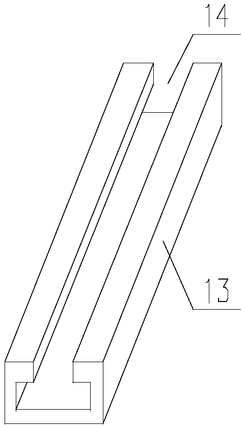
[0030] Such as Figure 1 to Figure 6 In the shown network transformer automatic detection device, on the basis of Embodiment 1, the distance between the first square pillar 3 and the second square pillar 4 is equal to the distance between the third square pillar 5 and the fourth square pillar 6 ; The spacing between the first square column 3 and the second square column 4 is equal to the length of the storage bar 13 . It also includes a pushing device 15 arranged on the table body 1 , the output end of the pushing device 15 is fixedly connected with a pushing block 16 , and the pushing block 16 faces between the first square column 3 and the second square column 4 . The light sources 12 are light emitting diodes. The line between the light sources 12 on one side of the track 2 is parallel to the axis of the track 2 . The second connecting rod 19 is fixed on the first connecting rod 17 through a push nut 20 . The opposite sides of the open end of the through hole 21 are prov...


PUM


Abstract

The present invention discloses a network transformer automatic detection device, which is used to solve the problem of low quality inspection efficiency of network transformer pins in the prior art to achieve the purpose of improving quality inspection efficiency of a network transformer through a photoelectric method. When the network transformer stays on a track in an inspection disk to performquality inspection, the light intensity on both sides is equal. When the network transformer pins are perfectly qualified, the intensity of light reflected by the pins to two sides is equal, and no glaring spot appears in an image captured by an image acquisition device directly above the inspection disk. If the pins are bent or buckling, the defects of the network transformer pins can be spottedon first sight. The network transformer automatic detection device can even perform exposure intensity analysis on the image through set-up program, thereby automatically performing quality inspection on the network transformer pins, hence quality inspection efficiency of the network transformer pins is greatly improved.

Description

technical field [0001] The invention relates to the field of network transformers, in particular to an automatic detection device for network transformers. Background technique [0002] Network transformers, also known as data pumps, network isolation transformers, etc., filter the differential signals output by the PHY with differential-mode coupled coil coupling to enhance the signals, and couple them to the other end of the network cable through electromagnetic field conversion. When any CMOS process chip is working, the signal level generated is always greater than 0V (depending on the chip process and design requirements), and the PHY output signal will have a large DC component loss if it is sent to a place of 100 meters or even longer. . Moreover, if the external network cable is directly connected to the chip, electromagnetic induction and static electricity can easily cause damage to the chip. Furthermore, the grounding method of the equipment is different, and th...

Claims


Application Information

Patent Timeline
Patent Type & Authority Applications(China)
IPC IPC(8): G01N21/88G01B11/00G01B11/24
CPCG01N21/8851G01B11/00G01B11/24G01N2021/8887
Inventor 黄建国黄旭
Owner ZHONGJIANG KAIXUN ELECTRONICS
Why Eureka
Try Eureka