
Fast charging device for storage battery system and water cooling system thereof

A storage battery system, fast charging technology, applied in the direction of battery circuit device, circuit device, arrangement of multiple synchronous batteries, etc., to achieve the effects of slowing down imbalance, benefiting balanced maintenance, and suppressing harmonics

Inactive Publication Date: 2018-10-19
NAVAL UNIV OF ENG PLA
View PDF8 Cites 2 Cited by
  • Summary
  • Abstract
  • Description
  • Claims
  • Application Information

AI Technical Summary

Problems solved by technology

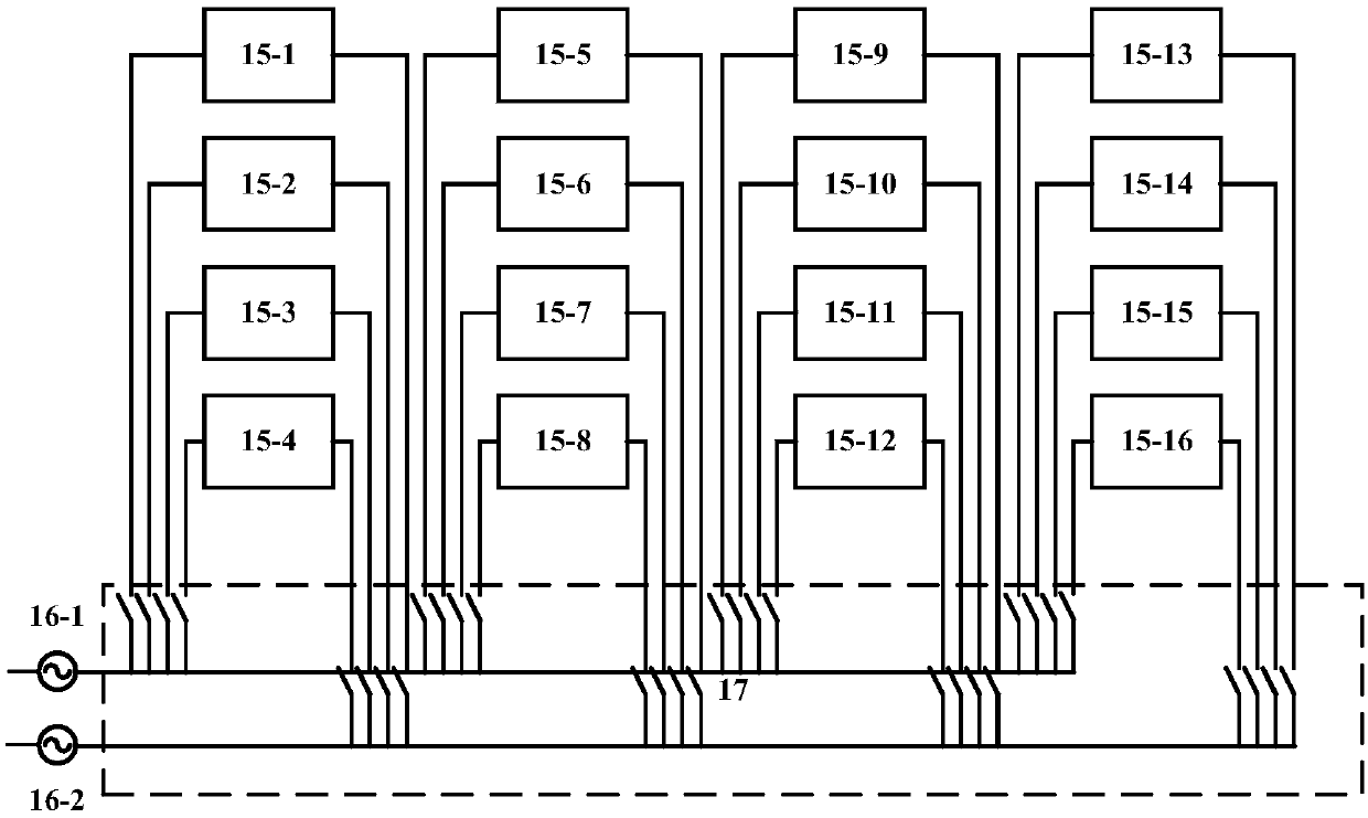
According to the method of the technical solution of the present invention, in view of the situation that the storage batteries need to be charged separately in groups, and the instantaneous high and low voltage changes during charging and discharging have great potential safety hazards, multiple charging devices are used to charge the storage batteries, and at the same time, an active filter is used to charge the entire battery. Harmonic suppression by the device group, and high-voltage and low-voltage protection by high-voltage DC relays can effectively improve the battery charging efficiency and improve the safety of the battery during charging and discharging.

Method used


Image

  • Fast charging device for storage battery system and water cooling system thereof
  • Fast charging device for storage battery system and water cooling system thereof

Examples


Embodiment Construction

[0032] In order to make the object, technical solution and advantages of the present invention clearer, the present invention will be further described in detail below in conjunction with the accompanying drawings and embodiments. It should be understood that the specific embodiments described here are only used to explain the present invention, not to limit the present invention. In addition, the technical features involved in the various embodiments of the present invention described below can be combined with each other as long as they do not constitute a conflict with each other. The present invention will be further described in detail below in combination with specific embodiments.

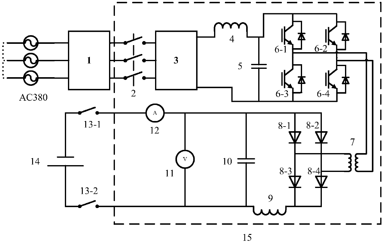
[0033] Such as figure 1Shown is a schematic diagram of the circuit structure of this embodiment. Including external power supply, active filter 1, AC contactor 2, three-phase uncontrolled rectifier bridge 3, first inductor 4, first capacitor 5, IGBT module 6 (AC conversion module), isolati...


PUM


Abstract

The invention discloses a fast charging device for a storage battery system so that an alternating-current power supply and a storage battery pack are connected by the fast charging device and thus the rapid charging of the battery pack can be realized. An active filter, an alternating-current contactor and a three-phase rectifier bridge are connected based on phases successively; an input inductor and the input capacitor are connected in series and then are connected to positive and negative terminals of the output terminal of the three-phase rectifier bridge; the input terminal of an alternating-current conversion module is connected to the two ends of the input capacitor; and the output terminal of the alternating-current conversion module is connected to the input terminal of an isolation transformer. A high voltage direct-current relay, an output capacitor and a battery pack are connected in series; one end of the output capacitor is connected to the cathode of a diode rectifier bridge through an output inductor and the other end is connected with the anode of the diode rectifier bridge; and the output terminal of the diode rectifier bridge is connected to the output terminalof the isolation transformer. Therefore, charging efficiency of the battery is improved and the safety of the storage battery during the charging and discharging processes is enhanced.

Description

technical field [0001] The invention belongs to the field of accumulator charging, and in particular relates to a fast charging device suitable for an accumulator system and a water cooling system thereof. Background technique [0002] The energy supply system for shipboard electromagnetic launch needs to have both high energy density and high power density, and consists of tens of thousands of single batteries connected in series and parallel. The rated voltage of the energy supply system is DC10KV, the grid energy supply interface is AC380V, and the instantaneous voltage of the battery system can reach DC15KV during the discharge process, so high and low voltage isolation is required during the charge and discharge process. Furthermore, the charging time of the entire battery system is 30 minutes, so it is necessary to use a charging device with fast charging to charge the battery pack. When the electromagnetic emission system is in the non-emission state, the battery sys...

Claims


Application Information

Patent Timeline
Patent Type & Authority Applications(China)
IPC IPC(8): H02J7/00H02J7/10H01M10/613H01M10/6567
CPCH01M10/613H01M10/6567H02J7/0014H02J7/027H02J7/06H02J2007/10Y02E60/10
Inventor 周仁鲁军勇龙鑫林魏静波柳应全吴羿延蔡喜元崔峻玮李松乘
Owner NAVAL UNIV OF ENG PLA
Learn More