Eureka AIR delivers breakthrough ideas for toughest innovation challenges, trusted by R&D personnel around the world.

Central heating system for segmented cooling of multipath backwater of circulating cooling water

A technology of cooling circulating water and segmented cooling, applied in hot water central heating system, heating system, household heating and other directions, can solve the problems of high consumption and difficult for heat users to ensure the temperature parameters of the process medium, and achieve energy saving, Solve the effect of equipment location and pipeline routing, reducing resource consumption

Active Publication Date: 2018-10-19
陈连祥
View PDF7 Cites 2 Cited by
  • Summary
  • Abstract
  • Description
  • Claims
  • Application Information

AI Technical Summary

Problems solved by technology

[0002] At present, the heat energy contained in the cooling process medium required by energy-consuming enterprises is mostly transferred from the water-cooled heat exchanger to the cooling circulating water, and discarded from the cooling tower to the environment. The discharge process consumes a lot of water, electricity, and chemical resources. This process makes the original Thermal energy that can be directly used becomes a huge burden for enterprises
Existing heat pump technology requires a large amount of investment, and driving energy is required for operation; although the "centralized heating system using cascaded condensation and cooling heat" can obtain heat energy that can be directly used, it requires the construction of a large number of pipelines and heat exchange equipment, while the medium water The impact on the process medium, the fluctuation of the heat user load is difficult to ensure the temperature parameters of the process medium and other reasons, so it is difficult to implement

Method used


Image

  • Central heating system for segmented cooling of multipath backwater of circulating cooling water
  • Central heating system for segmented cooling of multipath backwater of circulating cooling water
  • Central heating system for segmented cooling of multipath backwater of circulating cooling water

Examples


Embodiment 1

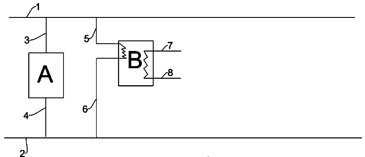
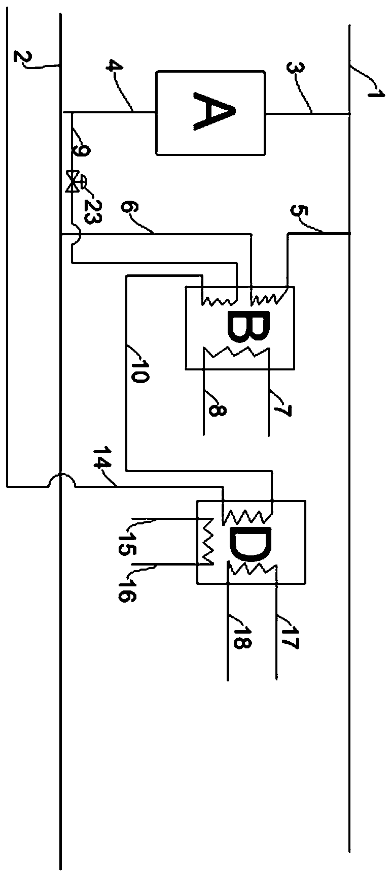
[0043] A centralized heating system with multi-return water segmental cooling of cooling circulating water, as shown in Figure 2(a), includes a cooling circulating water supply line 1 connected to a heat exchange device through a cooling circulating water supply line 3 of a heat exchanger A A, the cooling circulating water return line 2 is connected to the heat exchange device A through the cooling circulating water return line 4 of the heat exchanger A, and the cooling circulating water return line 4 of the heat exchanger A passes through the pipeline 9 to control the valve 23, heat exchange The high-temperature cooling circulating water supply pipeline 9 of the device B is connected to the heat exchange device B, and the heat exchange device B is connected to the waste heat energy deployment center D through the high-temperature cooling cycle water return line 10 of the heat exchanger B, and the waste heat energy deployment center D is through the deployment The high-temperat...

Embodiment 2

[0059] According to the method shown in embodiment 1, such as image 3 , characterized in that the waste heat energy allocation center D is connected to the water quality temperature monitoring and control equipment E through the high temperature cooling circulating water return pipeline 14 of the allocation center D, and the water quality temperature monitoring and control equipment E controls the valve 24 and the controller E through the pipeline 25 in turn. The cooling circulating water return line 25 is connected to the circulating water return line 2 , and the water quality temperature monitoring and control equipment E is connected to the heat exchange device B through the cooling circulating water closed circulation line 26 .

[0060] The cooling circulating water in the high-temperature cooling circulating water return line 14 of the deployment center D passes through the water quality temperature monitoring and control equipment E, and enters the heat exchange device B...

Embodiment 3

[0064] According to the method described in embodiment 1, it is characterized in that, as Figure 4 As shown, the heat exchange device B is connected to the reheater C through the high-temperature cooling circulating water return pipeline 10 of the heat exchanger B, and the reheater C is connected to the waste heat energy distribution center through the high-temperature cooling circulating water inlet pipeline 13 of the distribution center D d.

[0065] The reheater C is connected to the higher temperature process medium inlet pipeline 11 and the higher temperature process medium return pipeline 12 .

[0066] The high-temperature cooling circulating water in the high-temperature cooling circulating water return line 10 of the heat exchanger B enters the reheater C from the high-temperature cooling circulating water return line 10 of the heat exchanger B and continues to serve as a cooling cold source after heat exchange and heating The high-temperature cooling circulating wat...


PUM


Abstract

The invention relates to a central heating system for segmented cooling of multipath backwater of circulating cooling water. The system comprises a heat exchange device, a reheater, a waste heat energy allocating center and water quality and temperature monitoring control equipment. The system is characterized in that the circulating cooling water in a circulating water pipeline successively exchanges heat through the heat exchange device and the reheater to obtain directly used heat, heat is then released in the waste heat energy allocating center, and finally, a closed cycle is formed by means of the water quality and temperature monitoring control equipment. According to the system provided by the invention, waste heat of a process medium originally discharged to an environment througha cooling tower becomes a direct heat source output by the waste heat energy allocating center to surrounding heat consumers, so that a lot of energy sources used for heating are saved, and meanwhile,the resource consumption for treating the circulating cooling water is reduced greatly.

Description

technical field [0001] The invention designs a centralized heating system that uses energy-consuming enterprises to discharge condensation and cool heat energy through cooling circulating water. Specifically, it is a centralized heating system with multi-channel water return and section cooling of cooling circulating water. Background technique [0002] At present, the heat energy contained in the cooling process medium required by energy-consuming enterprises is mostly transferred from the water-cooled heat exchanger to the cooling circulating water, and discarded from the cooling tower to the environment. The discharge process consumes a lot of water, electricity, and chemical resources. This process makes the original The thermal energy that can be directly used becomes a huge burden for enterprises. Existing heat pump technology requires a large amount of investment, and driving energy is required for operation; although the "centralized heating system using cascaded co...

Claims


Application Information

Patent Timeline
Patent Type & Authority Applications(China)
IPC IPC(8): F24D3/18F24D3/10F24D19/10
CPCF24D3/1058F24D3/18F24D19/1015F24D19/1039Y02B30/12
Inventor 陈连祥陈克秀马琦轩黄博皓
Owner 陈连祥
Why Eureka
Eureka Blog
Learn More