Eureka AIR delivers breakthrough ideas for toughest innovation challenges, trusted by R&D personnel around the world.

Air conditioning cold water and hot water conveying and distribution system and method

A technology for hot and cold water and hot water, applied in air conditioning systems, space heating and ventilation, heating methods, etc., can solve problems such as high operating costs, high energy consumption, poor hydraulic stability, and achieve the effect of meeting the needs of water temperature

Inactive Publication Date: 2019-01-29
CHINA NORTHWEST ARCHITECTURE DESIGN & RES INST CO LTD
View PDF7 Cites 0 Cited by
  • Summary
  • Abstract
  • Description
  • Claims
  • Application Information

AI Technical Summary

Problems solved by technology

[0007] In order to overcome the disadvantages and deficiencies of high energy consumption, poor hydraulic stability, large initial investment and high operating cost obviously existing in the power centralized system in the above-mentioned prior art, the purpose of the present invention is to provide a kind of air-conditioning cold and hot water transmission and distribution system and method, which can greatly reduce the energy consumption of cold and hot water transportation, improve the hydraulic stability of the system, and reduce the initial investment and operating costs of the system

Method used


Image

  • Air conditioning cold water and hot water conveying and distribution system and method
  • Air conditioning cold water and hot water conveying and distribution system and method
  • Air conditioning cold water and hot water conveying and distribution system and method

Examples


Embodiment 1

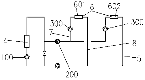
[0047] Refer to attached Figure 1-4 As shown, an air-conditioning cold and hot water distribution system in the present invention includes a cold and heat source device 4, wherein the cold and heat source device 4 is used to provide cold and hot water for air conditioning. Specifically, the cold and heat source device 4 is used to provide cold and hot water, that is, it provides cold water when cooling is required, and hot water when heating is required. Commonly used cold sources such as electric refrigeration chillers, lithium bromide absorption chillers, evaporative cooling chillers, etc., and heat sources such as boilers, municipal heating networks, geothermal water, etc.

[0048] Refer to attached image 3 As shown, in this embodiment, the cold and heat source device 4 forms a cold and hot station including the cold and heat source device 4 through pipelines, wherein the cold and hot station is used to provide cold and hot water to facilitate cooling or heating. In thi...

Embodiment 2

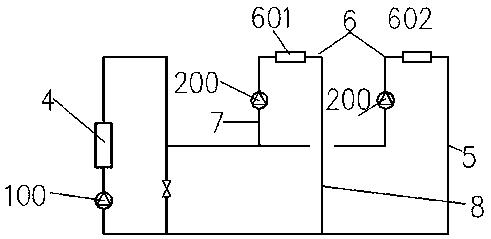
[0062] Refer to attached figure 2 As shown, as a further extension of the present invention, in this embodiment, when the distance is relatively short, only two-stage pumps can be provided, that is, only the first-stage pump 100 and the second-stage pump 200; the first-stage pump 100 is set An internal loop is formed in the cold and hot station of the cold and heat source device 4. At this time, the terminal equipment is directly connected to the cold and heat source device 4, and the main pipeline 5 is relatively short, so there is no need to arrange a pump; at this time, the second stage pump 200 is arranged on The terminal device is the user 6. In this embodiment, there are two users 6, the first user 601 and the second user 602. In this embodiment, the function of the first-stage pump is the same as that in Embodiment 1, and the combination of the first-stage pump 100 and the second-stage pump 200 jointly realizes the control of water supply to the user 6 . In the prior ...

Embodiment 3

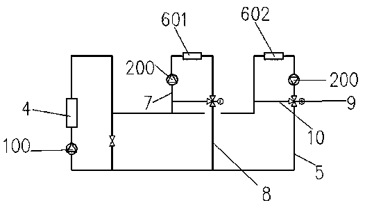
[0066] Refer to attached image 3 As shown, this embodiment adds a flow regulating valve 9 and a water mixing pipe 10 on the basis of embodiment 1, that is, this embodiment adds a water mixing function in the user 6 on the basis of embodiment 1.

[0067] Specifically, in this embodiment, a water mixing pipe 10 is added on the pipeline where the user 6's cold and hot water flow out, and the other end of the water mixing pipe 10 is connected to the water inlet end of the user 6, that is, the cold and hot water flowing out from the user 6 will be connected with the water inlet of the user 6. The mixing of cold and hot water before entering the user 6 changes the temperature of the water entering the user 6, thereby realizing the effect of temperature regulation. And the effect of flow regulating valve 9 is to control the flow of cold and hot water flowing out. By controlling this flow, for example, the temperature of the water flowing out is T2, and the temperature of water flowi...


PUM


Abstract

The invention relates to an air conditioning cold water and hot water conveying and distribution system and method. The system comprises a cold and hot source device and an N-stage pump, wherein the cold and hot source device is used for providing cold water and hot water for an air conditioner, the cold and hot source device forms a cold and hot station comprising a cold and hot source device through a pipeline, and the cold and hot station is used for providing cold water and hot water; N in the N-stage pump is a natural number larger than or equal to 3; the cold and hot source device passesthrough a main pipeline and a plurality of auxiliary pipelines to be connected with a tail end device; for the N-stage pump, a first-stage pump is arranged in the cold and hot station containing thecold and hot source device and is used for controlling generation of the cold water and the hot water in the cold and hot source device; a second-stage pump is arranged on the main pipeline, and is used for controlling conveying of the cold water and the hot water on the main pipeline, and controlling flow rates and pressure heads on the main pipeline at the same time; and pumps from the second-stage pump to the N-stage pump are used for jointly adjusting the flow rates and the pressure heads of the cold water and the hot water in the tail end device, so that distribution of the cold water andhot water generated from the cold and hot source device when the cold water and hot water enter the tail end device is controlled.

Description

technical field [0001] The invention relates to the technical field of heating, ventilating and air-conditioning, in particular to an air-conditioning cold and hot water transmission and distribution system and method. Background technique [0002] With the rapid development of the world economy, the resulting rapid growth of social energy consumption. In the total energy consumption of contemporary society, building energy consumption has always occupied a large proportion. At the same time, with the rapid economic development and the increasing level of urbanization, the building scale is getting larger and larger, and the use functions are also complex and changeable, and the scale and functional complexity of the heating and cooling systems are also increasing. The energy consumption of heating and cooling systems accounts for an increasing proportion of building energy consumption. At present, my country's heating energy consumption accounts for nearly 40% of the tota...

Claims


Application Information

Patent Timeline
Patent Type & Authority Applications(China)
IPC IPC(8): F24F5/00F24F11/46F24F11/84
CPCF24F5/0003F24F11/46F24F11/84
Inventor 周敏侯占魁
Owner CHINA NORTHWEST ARCHITECTURE DESIGN & RES INST CO LTD
Why Eureka
Eureka Blog
Learn More