
A full hydraulic reverse braking and clutching system

A reverse braking and full hydraulic technology, which is applied in the hydraulic field, can solve the problems of the transmission reducing the practical life of the transmission, insufficient power affecting the driver's operation, and failure to achieve the braking effect, so as to reduce the burden, improve the operating comfort, and improve the The effect of driving comfort and safety

Active Publication Date: 2020-02-18
ZHEJIANG HAIHONG HYDRAULIC TECH
View PDF8 Cites 0 Cited by
  • Summary
  • Abstract
  • Description
  • Claims
  • Application Information

AI Technical Summary

Problems solved by technology

[0006] The problem that exists regardless of forward or reverse braking is that during the braking process, the power of the vehicle is still output normally, causing the braking device to overcome the original inertia of the vehicle and convert the power of the vehicle to continue to accelerate, resulting in braking. The load of the moving device is too large to achieve an ideal braking effect, especially for engineering vehicles with large inertia and strong power.
[0008] However, during the running of the vehicle, due to the light braking during operation, the need to provide power immediately after the brake, or the need to use the engine to decelerate during the downhill process, only the Coordinated Control Strategy for Transmission and Braking Systems of Mining Vehicles "This batch of papers mentioned that cutting off the power output of the vehicle at the beginning of braking will lead to frequent transmission actions and reduce the practical life of the transmission, or the lack of power when the vehicle is in urgent need of power after braking will affect the normal operation of the driver. , even when the brake force is insufficient when going downhill, it will cause danger

Method used


Image

  • A full hydraulic reverse braking and clutching system
  • A full hydraulic reverse braking and clutching system
  • A full hydraulic reverse braking and clutching system

Examples


Embodiment 1

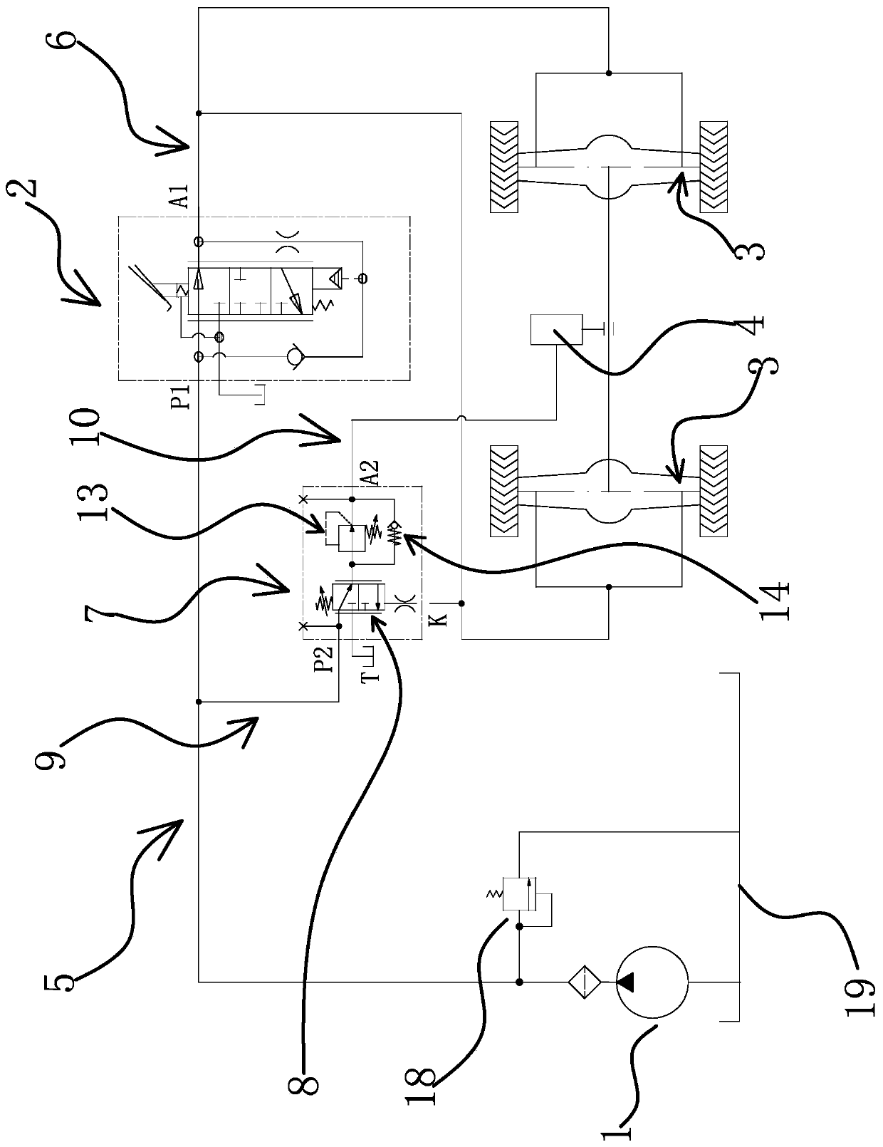
[0040] The full hydraulic reverse brake clutch system includes an oil pump 1, a brake valve 2, a brake 3, a transmission device 4 and a reverse brake clutch valve 7.

[0041] Specifically, as figure 1 As shown, the oil inlet end of the oil pump 1 is connected to the oil tank 19, and the oil outlet end is connected with the oil inlet P1 of the brake valve 2 through the oil inlet road-5, and a safety valve 18 is also arranged on the oil inlet road-5 to brake The working oil port A1 of the valve 2 communicates with the brake 3 through the working oil circuit-6. The brake valve 2 in this embodiment refers to a valve structure capable of reducing the oil pressure of the working oil passage-6 according to the increase of the stroke of the brake mechanism. The working oil circuit 16 supplies oil to the brake 3 to release the brake 3, and the brake 3 performs braking when the oil pressure of the working oil circuit 16 decreases. The reverse brake clutch valve 7 is between the oil pa...

Embodiment 2

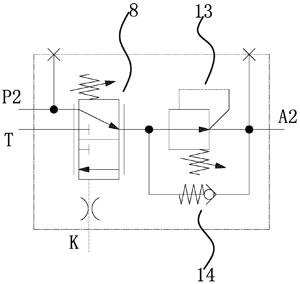
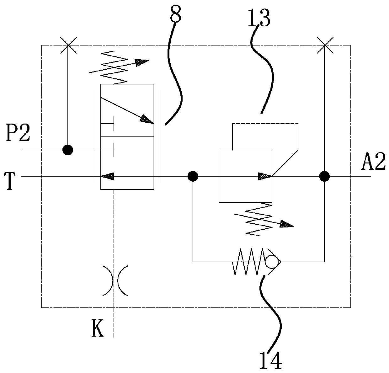
[0049] The technical solution in this embodiment is basically the same as the technical solution in the first embodiment, the difference is that in this embodiment, the reverse brake clutch valve 7 is an integral structure. Such as Figure 4 with Figure 5 As shown, the reverse brake clutch valve 7 also includes a valve body 15 , and the hydraulically controlled reversing valve 8 , pressure reducing valve 12 and one-way valve 14 are all arranged in the valve body 15 .

[0050] Such as Figure 5 As shown, the hydraulic control reversing valve 8 includes a reversing valve chamber 8b and a reversing valve core 8c slidingly arranged in the reversing valve chamber 8b. The reversing valve chamber 8b has an oil inlet groove 8b1, a working oil groove 8b2 and an oil return groove 8b3. The pressure reducing valve 12 includes a pressure reducing valve cavity 13b and a pressure reducing valve core 13c slidably disposed in the pressure reducing valve cavity 13b. The pressure reducing val...

Embodiment 3

[0055] The technical solution in the present embodiment is basically the same as the technical solution in the third embodiment, the difference is that in the present embodiment, such as Figure 5 As shown, the outer surface of the reversing valve core 8c has an oil return slot 8c1 that can communicate with the working oil tank 8b2 and the oil return tank 8b3. One end of the pressure reducing valve cavity 13b has a pressure reducing control oil cavity 13b3, and the pressure reducing valve core 13c has a The oil passage 13c1, one end of the oil passage 13c1 communicates with the decompression control oil chamber 13b3, and the other end communicates with the decompression valve chamber 13b through the oil passage 13c2 on the decompression valve core 13c, and the one-way valve chamber 14a is close to the return spring three One end of 14c communicates with the decompression oil tank 13b1, and communicates with the oil tank 13b2 and the working oil port 2 A2 through the decompressi...


PUM


Abstract

The invention provides a fully-hydraulic reverse braking clutch system, and belongs to the technical field of hydraulic pressure. The fully-hydraulic reverse braking clutch system solves the problem that the power cut-off time is difficult to control in the brake process of an existing braking system. The fully-hydraulic reverse braking clutch system comprises an oil pump, a braking valve, a brakeand a speed change gear; the braking valve communicates with the oil pump through a first oil inlet way, the braking valve communicates with the brake through a first working oil way, the braking valve controls the brake to conduct reverse braking, and a hydraulic-control reversing valve is arranged between the first oil inlet way and the brake; and a second oil inlet of the hydraulic-control reversing valve communicates with the first oil inlet way through a second oil inlet way, a second working oil opening communicates with a power cut-off control oil opening of the speed change gear through a second working oil way, the control oil opening communicates with the first working oil way, and when the pressure of the first working oil way is descended to the set value of the hydraulic-control reversing valve, the hydraulic-control reversing valve reverses to enable the second oil inlet way to communicate with the second working oil way. According to the fully-hydraulic reverse brakingclutch system, power can be cut off under the appropriate time in the brake process, and the driving comfort and safety of a vehicle are improved.

Description

technical field [0001] The invention belongs to the field of hydraulic technology, and relates to a full hydraulic brake clutch system, in particular to a full hydraulic reverse brake clutch system. Background technique [0002] The vehicle braking system refers to a device that forcibly reduces the speed of the vehicle. The braking system is mainly composed of an energy supply device, a control device, a transmission device and a brake. Its main function is to slow down or even stop a moving car, keep the speed of a downhill car stable, and keep a stopped car still. [0003] In the existing braking system, hydraulic pressure is a relatively common source of braking energy. Through the driver's operation of the control element, the pressure medium is transmitted to the transmission device and drives the brake to act to achieve braking. At present, the most common brake is the friction brake. The working principle is to use the frictional resistance generated when two moving...

Claims


Application Information

Patent Timeline
Patent Type & Authority Patents(China)
IPC IPC(8): B60T11/10B60T11/28
CPCB60T11/106B60T11/28
Inventor 何贤剑呼延宏高振家卢佩添
Owner ZHEJIANG HAIHONG HYDRAULIC TECH
Learn More