
Machining-use efficient derusting device for surface of steel plate

A technology for mechanical processing and steel plates, which is applied in the field of high-efficiency derusting devices for steel plate surfaces for mechanical processing, which can solve problems such as large labor load, low steel plate grinding efficiency, and unsatisfactory grinding quality, and achieve improved efficiency, low labor intensity and low labor load , significant effect

Active Publication Date: 2018-10-19
日照胜达机械股份有限公司
View PDF16 Cites 32 Cited by
  • Summary
  • Abstract
  • Description
  • Claims
  • Application Information

AI Technical Summary

Problems solved by technology

[0003] At present, there are many different types of grinding devices for machining on the market, but most of the grinding devices for machining need to manually adjust the position of the steel plate when grinding the steel plate, so as to realize the grinding and derusting of different positions of the steel plate by the grinding plate. This method not only has a large amount of labor, but also has a low grinding efficiency of the steel plate, the removal of rust stains on the surface of the steel plate is not sufficient and thorough, and the grinding quality is not satisfactory

Method used


Image

  • Machining-use efficient derusting device for surface of steel plate
  • Machining-use efficient derusting device for surface of steel plate
  • Machining-use efficient derusting device for surface of steel plate

Examples


Embodiment Construction

[0022] Below in conjunction with specific embodiment, the technical scheme of this patent is described in further detail:

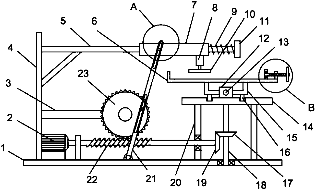
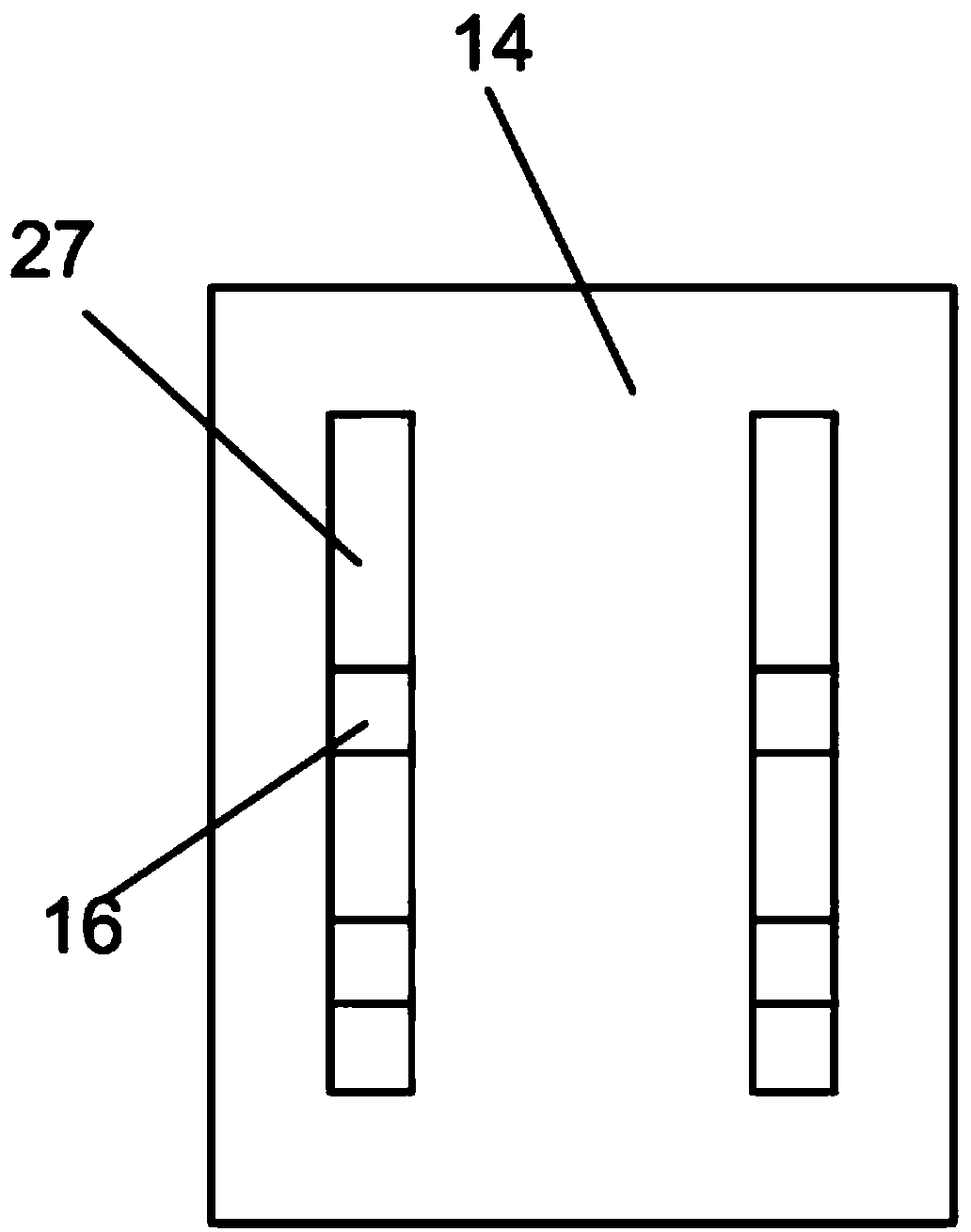
[0023] see Figure 1-6 , a high-efficiency derusting device for steel plate surfaces for mechanical processing, comprising a vertical plate 4 fixed vertically on the bottom plate 1, a guide rod 5 fixedly installed on the right side wall of the vertical plate 4, and a guide rod 5 fixedly installed on the bottom plate 1 Drive motor 2, the coaxial output shaft of drive motor 2 is fixedly installed with worm screw 22, horizontally fixedly installed with extension frame 3 on the vertical plate 4, and the extension frame 3 is provided with the worm gear 23 that meshes with worm screw 22 and is connected with rotation type. The bottom of the bottom plate 1 is rotatably provided with a swing strip 21, the swing strip 21 is provided with a first waist-shaped hole 29, and the worm wheel 23 is fixedly mounted with a first transmission pin 28 sliding through the firs...


PUM


Abstract

The invention discloses a machining-use efficient derusting device for the surface of a steel plate. The machining-use efficient derusting device comprises a bottom plate. A vertical plate is vertically and fixedly installed on the bottom plate. A guide rod is horizontally and fixedly installed on the right side wall of the vertical plate. Two guide sliding grooves are symmetrically formed in a supporting table. Limiting sliding blocks embedded in the guide sliding grooves in a sliding mode are vertically and fixedly installed at the bottom of a bearing plate. A hand wheel is fixedly installedat the right end of a lead screw. A driving motor serves as power output, a sliding sleeve plate reciprocates left and right along the guide rod through clockwise and anticlockwise alternating swinging of a swinging batten, and then repeated grinding derusting of a grinding disc in the horizontal transverse direction is realized. The rotation of an incomplete gear drives a concentric-square-shaped frame to reciprocate through a transmission inner rack, and the steel plate on the bearing plate reciprocates front and back relative to the grinding disc. Transverse grinding and longitudinal grinding are combined, grinding efficiency is greatly improved, the labor intensity and labor amount are low, and the derusting effect of the steel plate is remarkable.

Description

technical field [0001] The invention relates to the technical field of mechanical processing, in particular to a high-efficiency derusting device for steel plate surfaces used for mechanical processing. Background technique [0002] With the development of society, the speed of mechanical processing development continues to accelerate. In the process of mechanical processing, it is often necessary to grind steel plates. Grinding equipment for mechanical processing is a common equipment in the process of mechanical processing. [0003] At present, there are many different types of grinding devices for machining on the market, but most of the grinding devices for machining need to manually adjust the position of the steel plate when grinding the steel plate, so as to realize the grinding and derusting of different positions of the steel plate by the grinding plate. This method not only has a large amount of labor, but also has low grinding efficiency of the steel plate, the re...

Claims


Application Information

Patent Timeline
Patent Type & Authority Applications(China)
IPC IPC(8): B24B27/033
CPCB24B27/033
Inventor 盛梁科赵亚军钱正洪
Owner 日照胜达机械股份有限公司
Learn More