
High gain and high power density converter and commutation method for high and low voltage sides thereof

A high-power density, high-voltage side technology, applied in the field of converters, can solve the problems of complex coupled inductor process implementation, large current stress of power switch tubes, and not wide voltage adjustment range, so as to improve efficiency, power density, and reliability , The effect of reducing the volume of the magnetic core

Pending Publication Date: 2018-10-16
GUANGZHOU INST OF TECH
View PDF0 Cites 0 Cited by
  • Summary
  • Abstract
  • Description
  • Claims
  • Application Information

AI Technical Summary

Problems solved by technology

[0002] The high-gain DC converters that have appeared in recent years have made a lot of progress in improving power density, increasing gain, and soft switching. The realization of soft switching basically uses active clamping or passive clamping circuits, but in general The number of switching tubes used is too large, and the structure is complex, and the current stress of the power switching tubes is relatively large. In the resonant topology to realize the soft switching topology, there is also the problem of excessive resonant capacitor current. The current primary side power switching tubes have The source clamp or passive clamp circuit can achieve zero-voltage turn-on or zero-voltage turn-off, but it does not achieve zero-current turn-on, and the corresponding auxiliary branch switch is turned on after the corresponding main power switch is turned off; the useful switch The capacitor realizes the expansion of the transformer gain, but this method has an instantaneous current impact, and the number of switching capacitors required to achieve a high voltage output is large, the structure is complex, and the method of using a three-winding coupled inductor to achieve the expansion of the transformer gain , to solve the reverse recovery problem of the output diode, but the coupling inductor process of this method is complicated to realize, which is not conducive to industrial production. The adjustment of the voltage gain mainly depends on the change of the duty cycle of the primary power tube and the change of the transformer or coupled inductor. The change of the turn ratio is adjusted, the range of voltage adjustment is not wide, and the flexibility is not high

Method used


Image

  • High gain and high power density converter and commutation method for high and low voltage sides thereof
  • High gain and high power density converter and commutation method for high and low voltage sides thereof
  • High gain and high power density converter and commutation method for high and low voltage sides thereof

Examples


Embodiment Construction

[0052] Embodiments of the present invention will be described in detail below.

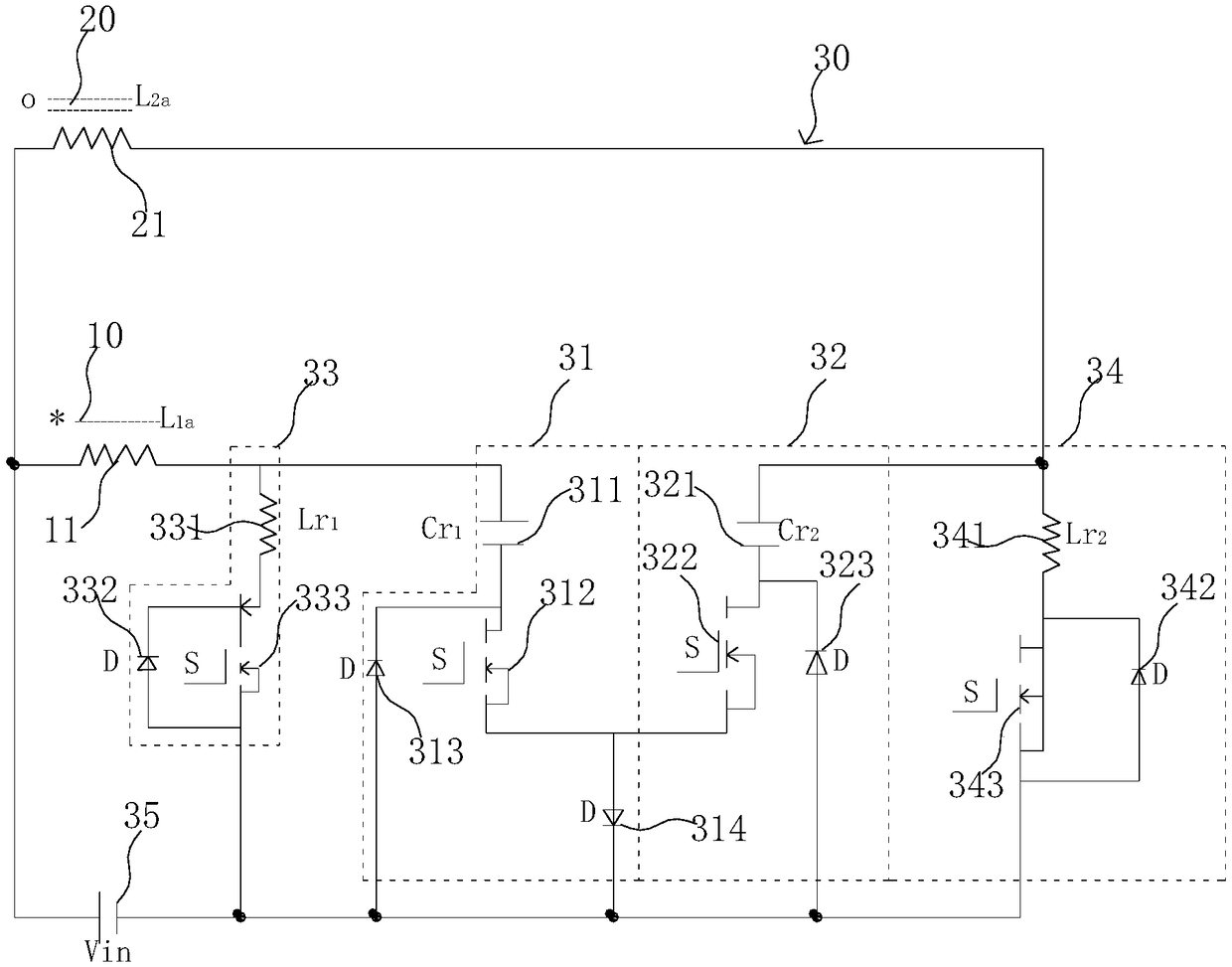
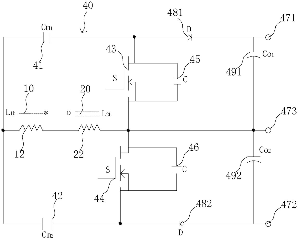
[0053] Such as figure 1 , figure 2 As shown, the high-gain high-power-density converter includes a first group of coupled inductors 10, a second group of coupled inductors 20, a converter low-voltage side circuit 30, and a converter high-voltage side circuit 40. The first group of coupled inductors 10 includes a first low-voltage side winding 11, the first high-voltage side winding 12, the second group of coupled inductors 20 includes the second low-voltage side winding 21, the second high-voltage side winding 22; the converter low-voltage side circuit 30 includes the first quasi-resonant soft switching circuit 31, the second Quasi-resonant soft switching circuit 32, first low-voltage branch 33, second low-voltage branch 34, low-voltage power supply 35, the end of the same name of the first low-voltage side winding 11 and the second low-voltage side winding 21 are respectively connected to the p...


PUM


Abstract

The invention discloses a high gain and high power density converter and commutation method for high and low voltage sides thereof. The high gain and high power density converter comprises a first setof coupled inductors, a second set of coupled inductors, a low voltage side circuit of the converter, and a high voltage side circuit of the converter. The high gain and high power density convertercan achieve zero voltage turning-off and zero current turning-on of all power switch tubes, which is similar to zero voltage turning-on. During the high-voltage side forward and reverse charging and discharging, a secondary side winding is shared, controllable power switch tube are used instead of forward and reverse charging diodes, and the output voltage is flexibly controlled by controlling a duty ratio of the controllable power switch tube, thereby broadening the control range and flexibility of the load output voltage; reducing circuit components, simplifying the structure, improving thepower density and reliability, and reducing costs.

Description

technical field [0001] The invention relates to the field of converters, in particular to a high-gain, high-power-density converter and a high-low voltage side commutation method thereof. Background technique [0002] The high-gain DC converters that have appeared in recent years have made a lot of progress in improving power density, increasing gain, and soft switching. The realization of soft switching basically uses active clamping or passive clamping circuits, but in general The number of switching tubes used is too large, and the structure is complex, and the current stress of the power switching tubes is relatively large. In the resonant topology to realize the soft switching topology, there is also the problem of excessive resonant capacitor current. The current primary side power switching tubes have The source clamp or passive clamp circuit can achieve zero-voltage turn-on or zero-voltage turn-off, but it does not achieve zero-current turn-on, and the corresponding ...

Claims


Application Information

Patent Timeline
Patent Type & Authority Applications(China)
IPC IPC(8): H02M3/335
CPCH02M3/33576H02M1/0058Y02B70/10
Inventor 桂存兵骆雪汇陈果
Owner GUANGZHOU INST OF TECH
Learn More