
A high-precision and lightweight triangular antenna panel and its manufacturing method

An antenna panel, triangular technology, applied in the direction of antenna, electrical components, etc., can solve the problems of easy generation of glue tumor, poor glue and air bubbles, difficult to control the overall accuracy of the structure, waste of manpower and equipment resources, etc., to reduce production raw materials, improve Installation accuracy and installation efficiency, and the effect of improving bonding efficiency

Active Publication Date: 2020-06-09
NO 54 INST OF CHINA ELECTRONICS SCI & TECH GRP
View PDF9 Cites 0 Cited by
  • Summary
  • Abstract
  • Description
  • Claims
  • Application Information

AI Technical Summary

Problems solved by technology

[0005] (1) These two inventive methods involve many moulds, such as "skin curved surface stretching die set, bone curved surface stretching die set, Z-shaped tendon stretching and bending die set", etc., the process is complicated and the production cycle is long; During the stretching process, a large amount of material waste in the clamping parts is caused
[0006] (2) Both of the two inventive methods use traditional riveted panels as the supporting structure, which tends to generate large internal stress during the riveting process, resulting in deformation of the riveted structure and making it difficult to control the overall precision of the structure
[0007] (3) Aluminum alloy plates and Z-shaped ribs have poor moldability during stretching, and are prone to springback deformation, and the accuracy after forming is difficult to guarantee
[0008] (4) Both of the two inventive methods use a large-area bonding process between the skin surface and the bone surface, which is prone to defects such as glue bumps, poor glue, and air bubbles, and there are hidden dangers in the bonding quality, resulting in a decrease in the reliability of the antenna panel
This not only wastes manpower and equipment resources, but also prolongs the installation period

Method used


Image

  • A high-precision and lightweight triangular antenna panel and its manufacturing method
  • A high-precision and lightweight triangular antenna panel and its manufacturing method
  • A high-precision and lightweight triangular antenna panel and its manufacturing method

Examples


Embodiment Construction

[0050] The present invention will be further described below in conjunction with the accompanying drawings and specific embodiments.

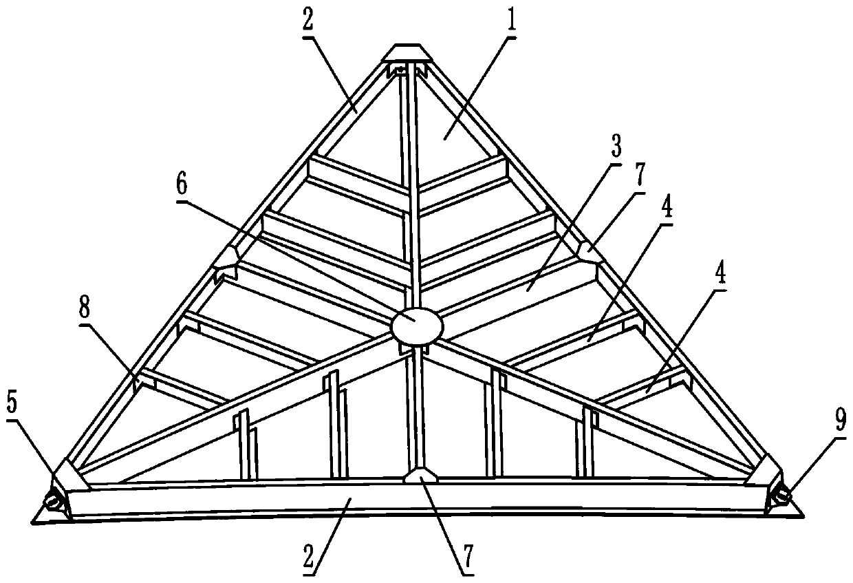
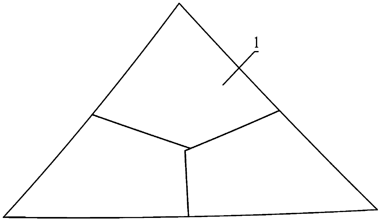
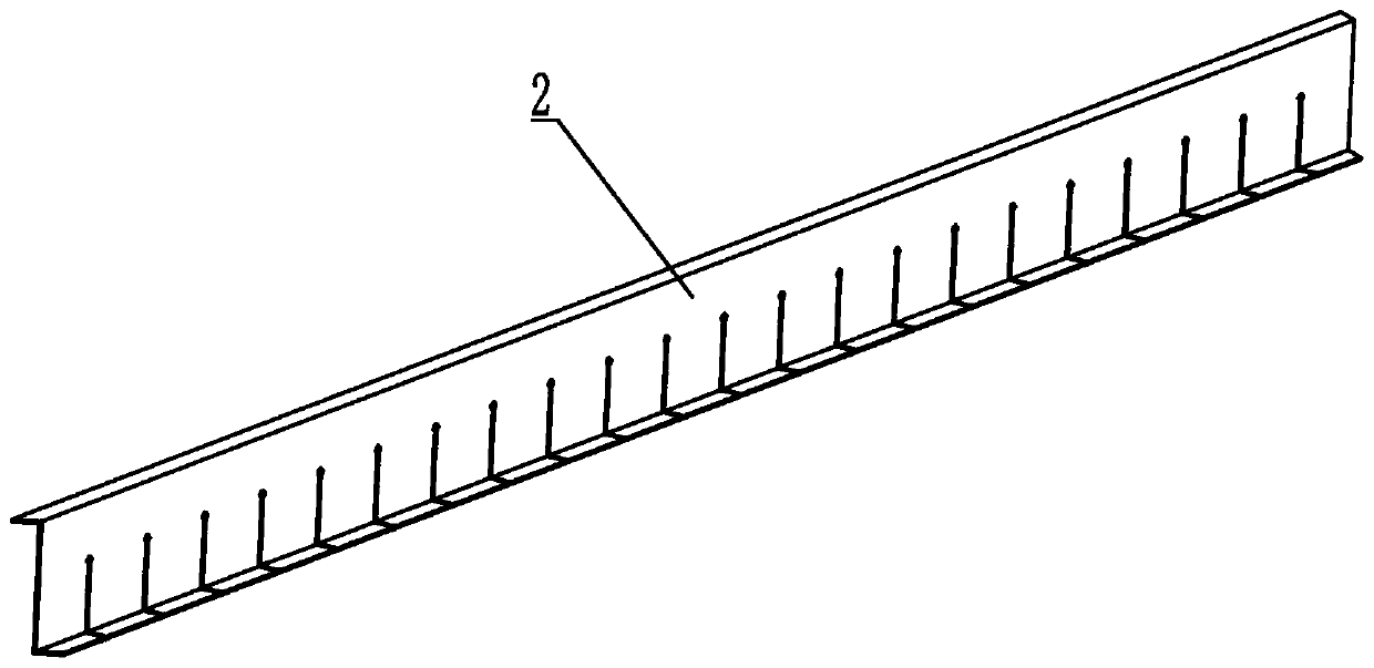
[0051] Such as Figure 1 to Figure 6 As shown, a triangular antenna panel includes a skin 1, a main side rib 2, a central rib 3, an auxiliary rib 4, a corner rib 5, a central connecting plate 6, an edge connecting plate 7, a corner piece 8 and a support 9; The skin 1 is triangular, and three main side ribs 2 are arranged on the three side directions of the convex surface of the skin 1; the central rib 3 is located on the midline of the three main side ribs 2; the auxiliary ribs 4 are distributed on both sides of the central rib 3 and The main side ribs 2 are vertical; the corner ribs 5 are arranged at the intersection of the main side ribs 2; the central connecting plate 6 is located at the intersection of the three central ribs 3; the edge connecting plate 7 is located at the midpoint of the three main side ribs 2 and connected to the central ri...


PUM


Abstract

The invention discloses a high-precision light-weight triangular antenna panel and a manufacturing method, relates to the design and manufacturing technologies of high-precision reflector antenna panels in the fields such as communication, measurement and control and radio astronomy, and aims to provide the antenna panel which is high in precision, light in weight and low in cost and is applicablefor batch production. The antenna panel comprises a skin, main side ribs, center ribs, auxiliary ribs, angle ribs, a center connecting plate, an edge connecting plate, angle supports and a support, wherein the skin is triangular; three main side ribs are arranged in the directions of three sides of the convex side of the skin; the center ribs are positioned on the center lines of the three main side ribs; the auxiliary ribs are distributed on two sides of the center ribs and are vertical to the main side ribs; the angle ribs are arranged at the intersection of the main side ribs; the center connecting plate is positioned at the intersection of the three center ribs; and vacuum negative pressure adsorption forming is adopted. The antenna panel is particularly applicable to designing and manufacturing panels of offset reflector antennas or circular symmetry reflector antennas which are high in precision and produced in batches.

Description

technical field [0001] The present invention relates to high-precision reflector antennas in the fields of communication, measurement and control, and radio astronomy, and more specifically, to panels of various apertures, high-precision circular symmetric reflector antennas or offset reflector antennas that work above the Ka frequency band design and fabrication methods. Background technique [0002] A reflector antenna usually consists of multiple antenna panels, and the surface accuracy of the antenna panel directly affects multiple electrical performance indicators. During the operation of the antenna, the panel is supported by the antenna back frame as a load. How to achieve light weight of the panel is also a problem that needs to be faced in the project when the surface accuracy is satisfied; the antenna panel needs to be adjusted many times during the installation process With measurement, therefore, reasonable design of panel shape and number of connection points i...

Claims


Application Information

Patent Timeline
Patent Type & Authority Patents(China)
IPC IPC(8): H01Q15/14
CPCH01Q15/14H01Q15/142
Inventor 刘国玺杜彪郑元鹏赵均红刘利文王海东杨晋蓉张一凡
Owner NO 54 INST OF CHINA ELECTRONICS SCI & TECH GRP
Learn More