Thermal conductivity meter for vacuum glass

A technology of vacuum glass and thermal conductivity meter, which is applied in the field of measuring instruments, can solve the problems of small thermal conductivity of vacuum glass, large error, and difficulty in finding insulation boards, etc., achieve good thermal insulation performance, and eliminate measurement errors and system errors.

Inactive Publication Date: 2018-10-16
QINGDAO TECHNOLOGICAL UNIVERSITY
View PDF6 Cites 0 Cited by
  • Summary
  • Abstract
  • Description
  • Claims
  • Application Information

AI Technical Summary

Problems solved by technology

Since the heat transfer coefficient of vacuum glass is very small, the error is very large when measured with an existing thermal conductivity meter. For example, when the heat transfer coefficient is less than 1, the measurement error is ±0.1. Theoretically, the heat transfer coefficient of vacuum glass The coefficient can be as small as 0.2, in which case the error of existing thermal conductivity meters is unacceptable
Although there are many devices and methods for measuring the heat transfer coefficient of vacuum glass in the prior art, such as patent applications CN02243245.0, CN200320126692.1, CN200620131674.6, CN200710003450.6, CN201210017369.4 and CN201210111168.0, etc., but for the same thickness For thermal insulation materials, the thermal conductivity of vacuum glass is the smallest, and it is difficult to find a better thermal insulation panel than vacuum glass, so the above devices and methods cannot solve the problem of measuring the heat dissipation of the thermal panel and provide a known accurate heat transfer coefficient or heat dissipation. Therefore, it is difficult to accurately measure the heat transfer coefficient of vacuum glass in the existing technology

Method used


Image

  • Thermal conductivity meter for vacuum glass
  • Thermal conductivity meter for vacuum glass

Examples


Embodiment Construction

[0033] The present invention will be described in further detail below in conjunction with the accompanying drawings.

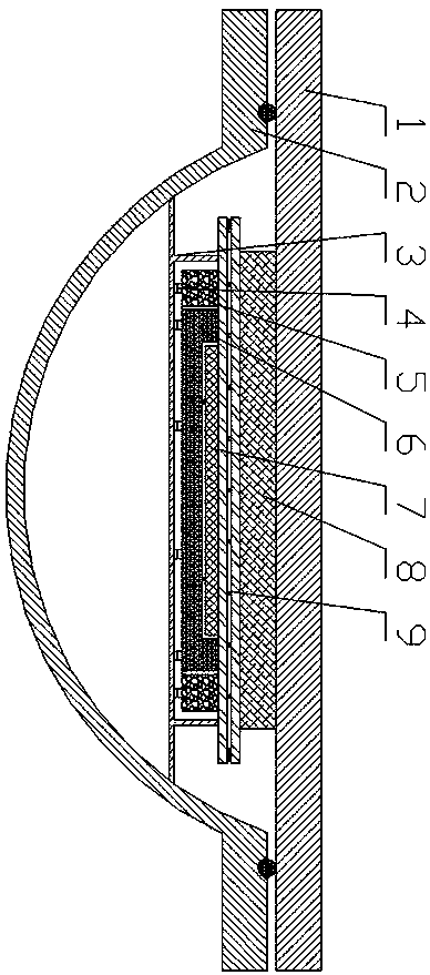
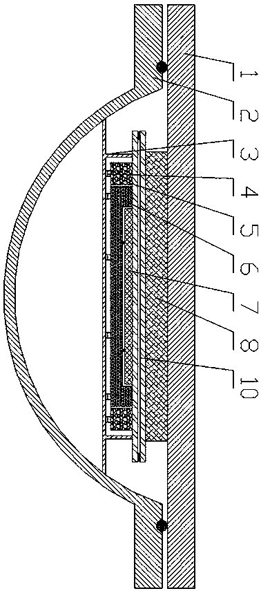
[0034] like figure 1 and figure 2 An embodiment of the present invention is shown. A vacuum glass thermal conductivity meter is composed of an upper shell 1 and a lower shell 2. After the upper shell 1 and the lower shell 2 are closed, they are sealed by a rubber sealing ring, and the inside is sealed by a vacuum. The system forms a high vacuum; the hot plate is composed of a protective hot plate 5, a buffer hot plate 6 and a measuring hot plate 7, which are installed in the chassis 3 through the heat insulating support 4, and the heat insulating support 4 is elastic, so that the hot plate can be in close contact with the vacuum glass; The inner surface of the chassis 3 is a low-emissivity surface (aluminum, silver or gold, or aluminum foil, etc.), which can insulate radiant heat, and the chassis 3 is installed in the lower shell 2 for heat insulation; the ...


PUM

PropertyMeasurementUnit
diameteraaaaaaaaaa

Abstract

A thermal conductivity meter for vacuum glass comprises an upper shell, a lower shell, a cold plate, a hot plate, a vacuum system and a control system, the cold plate and the hot plate are placed in asealed space formed by the upper shell and the lower shell, and vacuum glass to be measured is arranged between the cold plate and the hot plate; the upper shell is a flat plate, is in close contactwith the cold plate, and can serve as a radiator for the cold plate; and after the upper shell and the lower shell are closed, the formed sealed space is pumped into a high vacuum by the vacuum system, and the high vacuum has a better thermal insulation performance than the vacuum glass, and provides standard correction. The thermal conductivity meter can solve the heat dissipation problem of themeasurement hot plate and the provision problem of a correction standard plate, and has the characteristics of simple structure, convenience in measurement, and accuracy in data.

Description

technical field [0001] The invention relates to a measuring instrument, in particular to a vacuum glass thermal conductivity meter. Background technique [0002] Vacuum glass is one of the best energy-saving glasses, and its thermal insulation performance is generally expressed by the heat transfer coefficient, which can be obtained through heat conduction. Since the heat transfer coefficient of vacuum glass is very small, the error is very large when measured with an existing thermal conductivity meter. For example, when the heat transfer coefficient is less than 1, the measurement error is ±0.1. Theoretically, the heat transfer coefficient of vacuum glass The coefficient can be as small as 0.2, in which case the error of existing thermal conductivity meters is unacceptable. Although there are many devices and methods for measuring the heat transfer coefficient of vacuum glass in the prior art, such as patent applications CN02243245.0, CN200320126692.1, CN200620131674.6, C...

Claims


Application Information

Patent Timeline
Patent Type & Authority Applications(China)
IPC IPC(8): G01N25/20
CPCG01N25/20
Inventor 戴长虹
Owner QINGDAO TECHNOLOGICAL UNIVERSITY
Why Eureka
Try Eureka