Vibrating optical path assembly, and laser induced breakdown spectrometer with assembly

A spectrometer and component technology, applied in the field of spectral analysis, can solve the problems of complex mechanism, low moving speed, high driving power consumption requirements, etc., achieve high collection efficiency and meet the effect of miniaturization

Active Publication Date: 2018-10-16
VELA OPTOELECTRONICS SUZHOU CO LTD
View PDF14 Cites 0 Cited by
  • Summary
  • Abstract
  • Description
  • Claims
  • Application Information

AI Technical Summary

Problems solved by technology

This technical solution is relatively similar to the technical solutions of the two patents with publication numbers US7595873 and US8436991, and does not overcome the defects of the above technical solutions, and the structure is relatively complicated
[0009] To sum up, in the existing optical path design scheme for laser-induced breakdown spectrometers, the mechanical structure required to realize the movement of the spot is relatively large, and the movement speed is low, so it is impossible to achieve high-frequency reciprocating motion
In addition, the above-mentioned technical solutions generally have the defects of complex mechanism and high requirements for driving power consumption
[0010] Therefore, under the current miniaturization trend of laser-induced breakdown spectrometers, such as the optical path design of miniaturized handheld laser-induced breakdown spectrometers, the existing related optical path design schemes cannot achieve fast reciprocating spot movement, and cannot adapt to Miniaturization requirements for institutional volume and complexity

Method used


Image

  • Vibrating optical path assembly, and laser induced breakdown spectrometer with assembly
  • Vibrating optical path assembly, and laser induced breakdown spectrometer with assembly
  • Vibrating optical path assembly, and laser induced breakdown spectrometer with assembly

Examples


Embodiment Construction

[0058] Typical embodiments embodying the features and advantages of the present invention will be described in detail in the following description. It should be understood that the present invention can have various changes in different embodiments without departing from the scope of the present invention, and that the description and drawings therein are illustrative in nature and not intended to limit the present invention. invention.

[0059] In the following description of various exemplary embodiments of the invention, reference is made to the accompanying drawings, which form a part hereof, and in which are shown by way of example different exemplary structures, systems, and embodiments in which aspects of the invention may be implemented and steps. It is to be understood that other specific arrangements of components, structures, exemplary means, systems and steps may be utilized and structural and functional modifications may be made without departing from the scope o...


PUM


Abstract

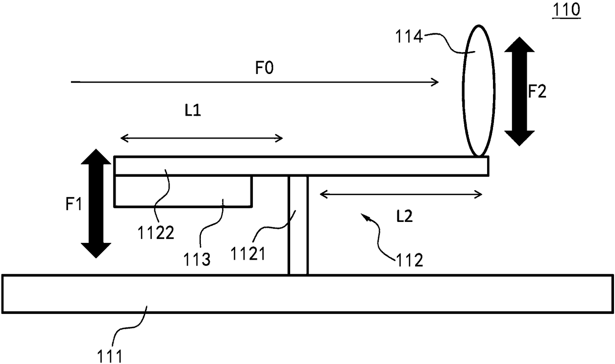
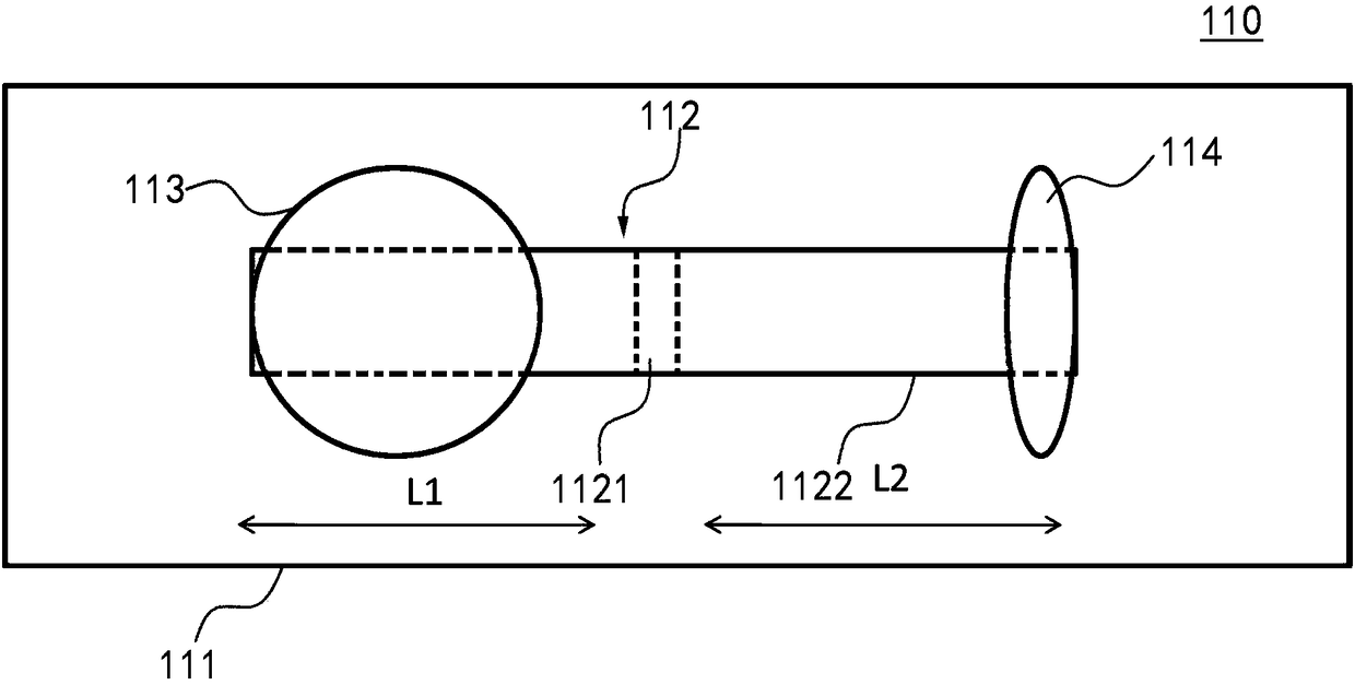
The invention discloses a vibrating optical path assembly, and a laser induced breakdown spectrometer with the assembly. The vibrating optical path assembly comprises an optical platform, a cantilever, a vibration generating device and an optical lens; the cantilever comprises a vertical arm arranged on the optical platform and a transverse arm arranged on the vertical arm, and at least one of the vertical arm and the transverse arm is made of an elastic material; the vibration generating device is arranged on the cantilever, and configured to adjustably generate a first vibration; the optical lens is arranged on the cantilever and is configured to allow lights to go through in order to form a light spot; and the first vibration is transmitted to the optical lens by the cantilever in order to generate a second vibration, and the lights go through the vibrating optical lens to generate a light spot movement phenomenon. The cantilever is used to transmit the vibration generated by the vibration generating device to the optical lens to make the lights, optically transmitted by the optical lens, form the light spot on the surface of a measured substance in order to generate the lightspot movement phenomenon, so the sampling area is increased, the generation of stable plasma is kept, thereby the quantitative analysis with excellent repeatability and accuracy becomes possible.

Description

technical field [0001] The invention relates to the technical field of spectrum analysis, in particular to a vibrating optical path assembly and a spectrometer with the structure. Background technique [0002] Laser Induced Breakdown Spectroscopy (LIBS for short) is a new analytical method in the field of spectral analysis. Generally speaking, the principle of the existing laser-induced breakdown spectrometer can be summarized as an analytical method based on atomic emission spectroscopy for qualitative and quantitative analysis of the components of the measured substance. Wherein, the above-mentioned measured substances may be solid, liquid or gaseous. For example, when the measured substance is solid, a beam of high-energy pulsed laser is optically focused on the surface of the solid measured substance, vaporizes a small part of the measured substance and peels off its surface to form plasma, that is, the plasma state of the tested substance. After the emission of the p...

Claims


Application Information

Patent Timeline
Patent Type & Authority Applications(China)
IPC IPC(8): G01N21/73G01N21/01
CPCG01N21/01G01N21/73G01J3/443G01J3/0208G01J3/0202G01N21/718G02B26/0875G01N2201/06113G02B7/02
Inventor 孙嵘郭伟
Owner VELA OPTOELECTRONICS SUZHOU CO LTD
Why Eureka
Try Eureka