
Energy-saving white smoke plume removal device applicable to small and medium-sized boilers

An energy-saving, small and medium-sized technology, applied in the field of flue gas purification, can solve the problems of high operation and maintenance cost, easy corrosion and blockage of equipment, large equipment investment, etc., and achieve the effect of convenient operation and maintenance, less installation work, and small volume.

Pending Publication Date: 2018-10-16
宁波国电龙高科环境工程技术有限公司
View PDF1 Cites 0 Cited by
  • Summary
  • Abstract
  • Description
  • Claims
  • Application Information

AI Technical Summary

Problems solved by technology

[0007] In order to solve the problems of the existing flue gas dewhitening device, such as complex structure, large equipment investment, easy corrosion and blockage, unstable operation and high operation and maintenance costs, the present invention further provides an energy-saving flue gas filter suitable for small and medium-sized boilers. Whitening device

Method used


Image

  • Energy-saving white smoke plume removal device applicable to small and medium-sized boilers
  • Energy-saving white smoke plume removal device applicable to small and medium-sized boilers
  • Energy-saving white smoke plume removal device applicable to small and medium-sized boilers

Examples


specific Embodiment approach 1

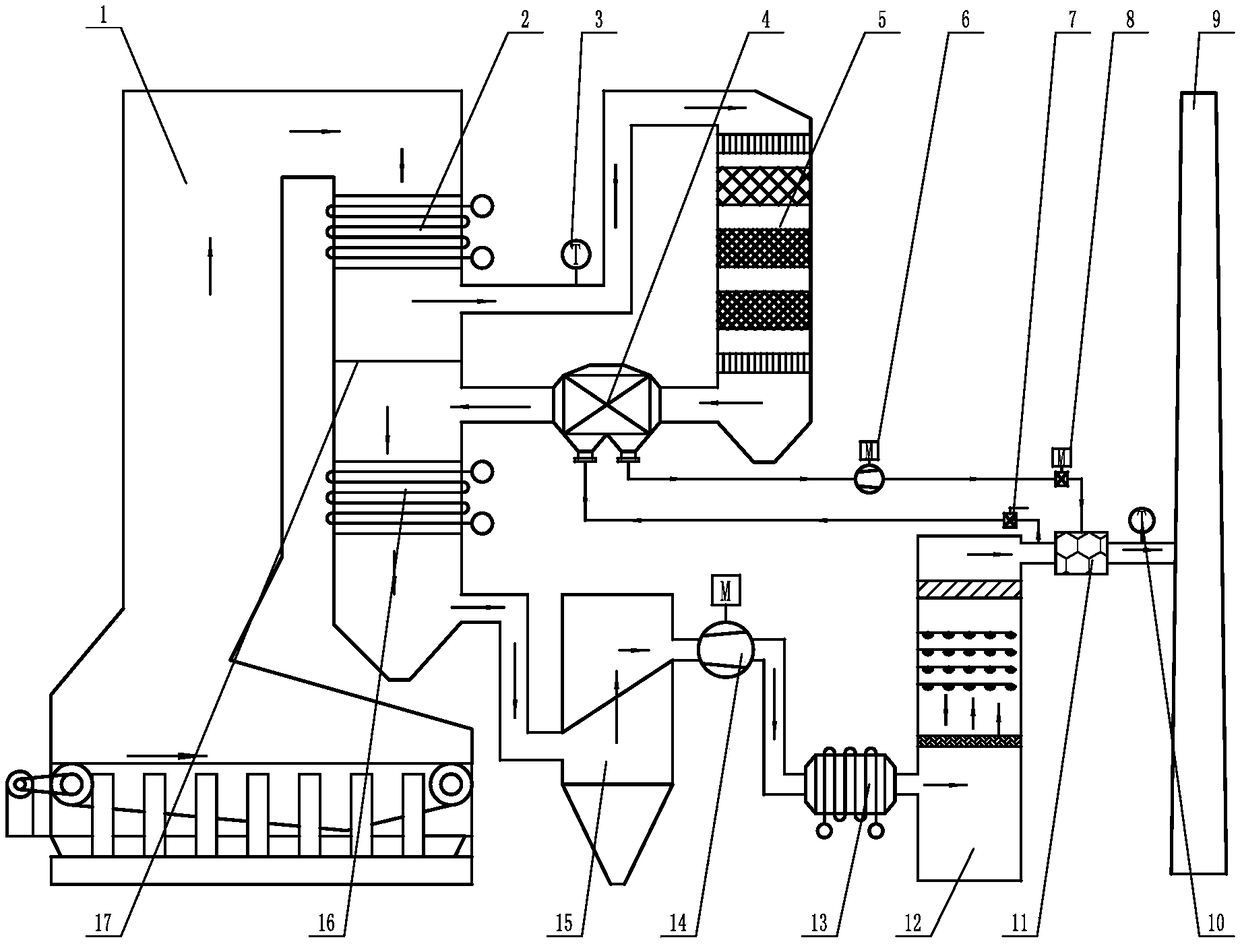
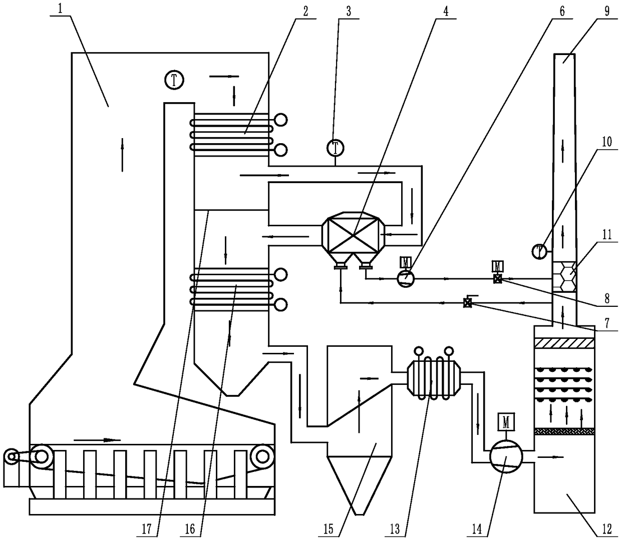
[0025] Specific implementation mode one: as figure 1 and image 3 As shown, the energy-saving flue gas dewhitening device suitable for small and medium-sized boilers in this embodiment includes a temperature transmitter 3, a heat exchanger 4, an SCR reactor 5, an ultra-low temperature economizer 13, a hot flue gas fan 6, a cooling Flue gas valve 7, hot flue gas electric valve 8, temperature controller 10 and mixer 11, a flue partition 17 is arranged between the first economizer 2 and the second economizer 16, the SCR reactor 5 and the boiler The outlet of the upper flue of 1 is connected, the temperature transmitter 3 is set on the pipeline between the SCR reactor 5 and the boiler 1, the outlet of the SCR reactor 5 is connected with the inlet of the lower flue of the boiler 1 through the heat exchanger 4, and the mixing The device 11 is set at the outlet of the ultra-clean desulfurization equipment 12 and the two are connected to each other. The lower end of the heat exchange...

specific Embodiment approach 2

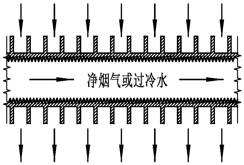
[0031] Specific implementation mode two: as image 3 As shown, the heat exchanger 4 in this embodiment is a tube heat exchanger. With such a design, the high-temperature flue gas flows outside the heat exchange tube, and the clean flue gas flows in the heat exchange tube. The high-temperature flue gas and the clean flue gas are mixed and arranged. The gas section is downstream. Other components and connections are the same as those in the first embodiment.

specific Embodiment approach 3

[0032] Specific implementation mode three: as figure 1 and image 3 As shown, the inner wall of the heat exchange tube of the heat exchanger 4 in this embodiment is processed with internal threads, and the outer wall of the heat exchange tube of the heat exchanger 4 is uniformly provided with fins along its length direction. This design greatly increases the heat exchange area and reduces the material consumption of the heat exchanger. The external high-temperature flue gas contains smoke and dust, and the anti-clogging and anti-wear fins are used to increase the heat exchange area. The internal flue gas is clean and dust-free. Other components and connections are the same as those in the second embodiment.


PUM


Abstract

The invention relates to a white smoke plume removal device, in particular to an energy-saving white smoke plume removal device applicable to small and medium-sized boilers and solves the problems that existing white smoke plume removal devices are complex in structure, large in equipment investment, prone to corrosion and blockage, instable in operation and high in operation and maintenance cost.An outlet of an SCR reactor is communicated with a lower flue inlet of a boiler through a heat exchanger, a mixer is arranged at an outlet of an ultraclean desulfurization device and communicated with the ultraclean desulfurization device, the lower end of the heat exchanger is connected with a clean cold smoke pipeline and a clean hot smoke pipeline, the other end of the clean cold smoke pipeline is communicated with the outlet of the ultraclean desulfurization device, the other end of the clean hot smoke pipeline is communicated with an inlet of the mixer, a cold smoke valve is arranged onthe clean cold smoke pipeline, a hot smoke fan and a hot smoke electric valve are arranged on the clean hot smoke pipeline, a temperature controller is arranged at an outlet of the mixer, and an ultralow-temperature economizer is arranged on a flue between an induced draft fan and the ultraclean desulfurization device. The energy-saving white smoke plume removal device is applicable to energy-saving white smoke plume removal of the small and medium-sized boilers.

Description

technical field [0001] The invention relates to a flue gas dewhitening device, in particular to an energy-saving desulfurized flue gas dewhitening device suitable for industrial boilers or kilns, and belongs to the technical field of flue gas purification. Background technique [0002] After the wet desulfurization technology has been vigorously promoted in China, the project has experienced the development process of GGH for the reheating of the wet saturated flue gas after desulfurization, the anti-corrosion flue gas of the chimney is no longer hot, and the flue gas dewhitening treatment. [0003] Existing desulfurization flue gas whitening technology, some use the existing GGH device, use the flue gas before desulfurization after dust removal to heat the wet flue gas after desulfurization; some upgrade the existing GGH technology, adopt a new type MGGH flue gas dewhitening device; GGH device has large investment in equipment, risks of flue gas leakage, equipment corrosion...

Claims


Application Information

Patent Timeline
Patent Type & Authority Applications(China)
IPC IPC(8): B01D53/86B01D53/56F23J15/06
CPCB01D53/8631F23J15/06B01D2258/0283Y02E20/30
Inventor 王帅姜志华杜大全马伟王强张岩孙国禹孙涛
Owner 宁波国电龙高科环境工程技术有限公司
Learn More