A grouting sleeve processing device

A processing device and a technology of grouting sleeves, which are applied to building reinforcements, buildings, building components, etc., can solve the problems of time-consuming and material-consuming, complex processing of grouting sleeves, etc., and achieve the effects of reducing wall thickness, saving materials, and simple structure

Active Publication Date: 2020-11-03
德睿盛兴(大连)装配式建筑科技有限公司
View PDF6 Cites 0 Cited by
  • Summary
  • Abstract
  • Description
  • Claims
  • Application Information

AI Technical Summary

Problems solved by technology

[0003] In order to overcome the traditional grouting sleeve processing complex, time-consuming and material-consuming problems, the invention provides a grouting sleeve processing device, the grouting sleeve processing device includes a fixed sleeve, a scoring mechanism and a connecting plate, the scoring The mechanism includes a first clamping plate, a second clamping plate and a scoring plate; the first clamping plate is fixedly arranged outside the fixing sleeve, the scoring plate is fixed on the first clamping plate through a pin shaft, and one end of the scoring plate is fixed by The gap provided on the sleeve extends into the cavity of the fixed sleeve, the other end of the scoring plate is connected to the second splint through the pin shaft, the second splint and the connecting plate are hinged through the connecting plate, and one end of the fixed sleeve is provided with Hydraulic cylinder, the hydraulic rod protruding from the hydraulic cylinder is connected to the connecting plate; when making the grouting sleeve, put the seamless steel pipe of appropriate length into the fixed sleeve cavity, start the hydraulic cylinder, and the hydraulic rod of the hydraulic cylinder stretches out to drive The scoring mechanism moves, the scoring plate rotates, and the part of the scoring plate that extends into the cavity of the fixed sleeve through the gap dents the seamless steel pipe, restores the hydraulic cylinder, and the hydraulic rod retracts to drive the scoring mechanism to reset. The seamless steel pipe with dents can be taken out to complete the processing process

Method used


Image

  • A grouting sleeve processing device
  • A grouting sleeve processing device
  • A grouting sleeve processing device

Examples


Embodiment Construction

[0016] The following will clearly and completely describe the technical solutions in the embodiments of the present invention with reference to the accompanying drawings in the embodiments of the present invention. Obviously, the described embodiments are only some, not all, embodiments of the present invention. Based on the embodiments of the present invention, all other embodiments obtained by persons of ordinary skill in the art without making creative efforts belong to the protection scope of the present invention.

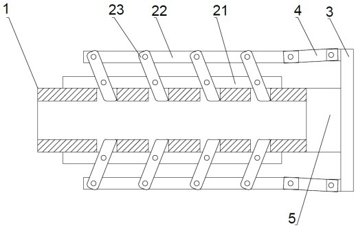
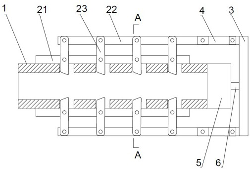
[0017] see Figure 1-3 , the present invention provides a grouting sleeve processing device, the grouting sleeve processing device includes a fixed sleeve 1, a scoring mechanism and a connection plate 3, and the scoring mechanism includes a first clamping plate 21, a second clamping plate 22 and Scoring plate 23; the first clamping plate 21 is fixedly arranged on the outside of the fixing sleeve 1, the scoring plate 23 is fixed on the first clamping plate 21 t...


PUM


Abstract

The invention provides a grouting sleeve machining device. The grouting sleeve machining device comprises a fixing sleeve (1), a nicking mechanism and a connecting disc (3); the nicking mechanism comprises a first clamping plate (21), a second clamping plate (22) and a nicking plate (23); the first clamping plate (21) is fixedly arranged outside the fixing sleeve (1); and the nicking plate (23) isfixed to the first clamping plate (21) through a pin shaft, and one end of the nicking plate (23) stretches into a cavity of the fixing sleeve (1) through a notch groove formed in the fixing sleeve (1). A grouting sleeve is formed at a time when being machined through the grouting sleeve machining device, the structure is simple, and the working efficiency of machining the grouting sleeve is effectively improved; under the premise that the rigidity of a sleeve body is met, the wall thickness of the sleeve body can be decreased properly through the grouting sleeve manufactured by the groutingsleeve machining device, and thus materials are saved; and meanwhile, the wall thickness is decreased under the situation of the same outer diameter, grouting materials are increased, thus grouting ismore dense, and bonding performance is higher.

Description

technical field [0001] The invention belongs to the technical field of construction engineering, and in particular relates to a grouting sleeve processing device. Background technique [0002] In the prior art, the steel bar connection between the prefabricated concrete building parts needs to be connected by sleeve grouting. The two connected steel bars are inserted into the metal sleeve and high-performance cement mortar is poured into the gap between the sleeve and the steel bar. After the cement mortar is hardened, the three are embedded with each other to realize the connection of the steel bars. The traditional grouting sleeve is provided with protruding anchors on the inner wall of the sleeve. The common method is to weld the anchors to the inner wall of the sleeve or open a mold to cast the anchors and the casing as one. The processing methods of these anchors are not only relatively Complicated and time consuming. There is also no device for processing the groutin...

Claims


Application Information

Patent Timeline
Patent Type & Authority Patents(China)
IPC IPC(8): E04C5/16
CPCE04C5/165
Inventor 徐世大
Owner 德睿盛兴(大连)装配式建筑科技有限公司
Why Eureka
Try Eureka