
Device for artistic engraving

A kind of art and knife handle technology, applied in the field of engraving, can solve the problems that the carving knife cannot be polished, the knife head is easy to loose, and the debris cannot be blown out.

Active Publication Date: 2018-10-12
CHONGQING IND POLYTECHNIC COLLEGE
View PDF9 Cites 2 Cited by
  • Summary
  • Abstract
  • Description
  • Claims
  • Application Information

AI Technical Summary

Problems solved by technology

[0009] The object of the present invention is to provide a device for art carving, which solves the problem that in the prior art, the carving knife cannot grind the side wall of the carving gap after carving; the debris in the carving gap cannot be blown out in time; , the problem that the cutter head is easy to loose

Method used


Image

  • Device for artistic engraving
  • Device for artistic engraving
  • Device for artistic engraving

Examples


Embodiment 1

[0040] The specific implementation process is as follows:

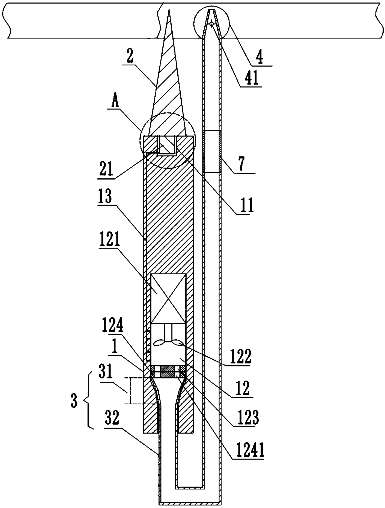
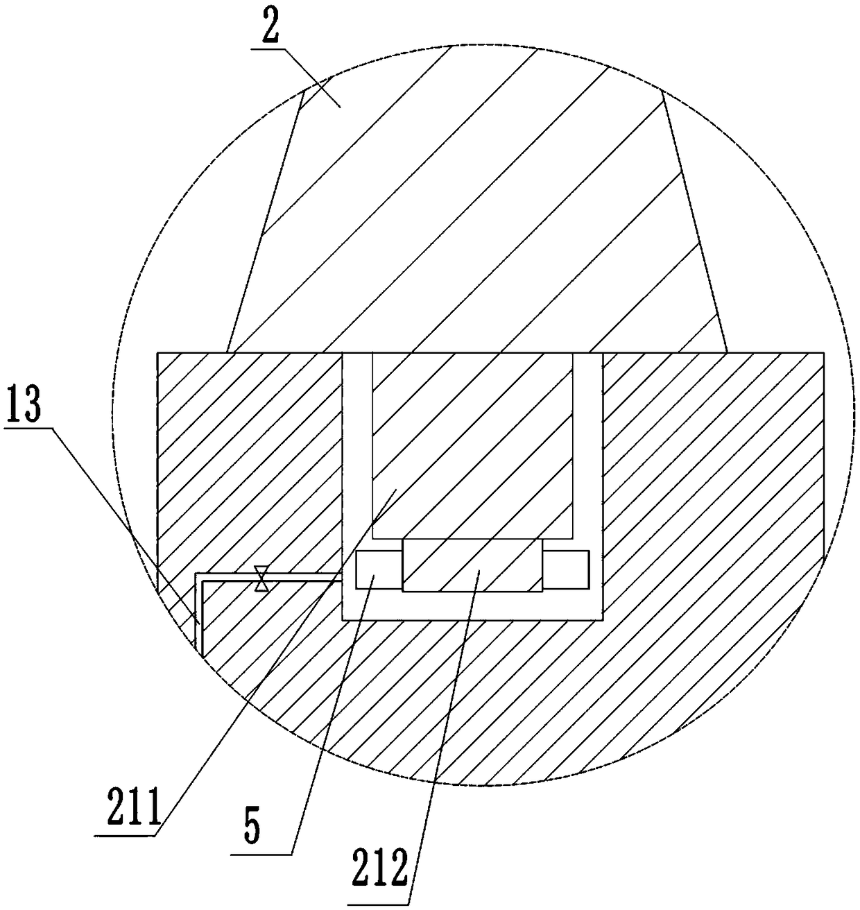
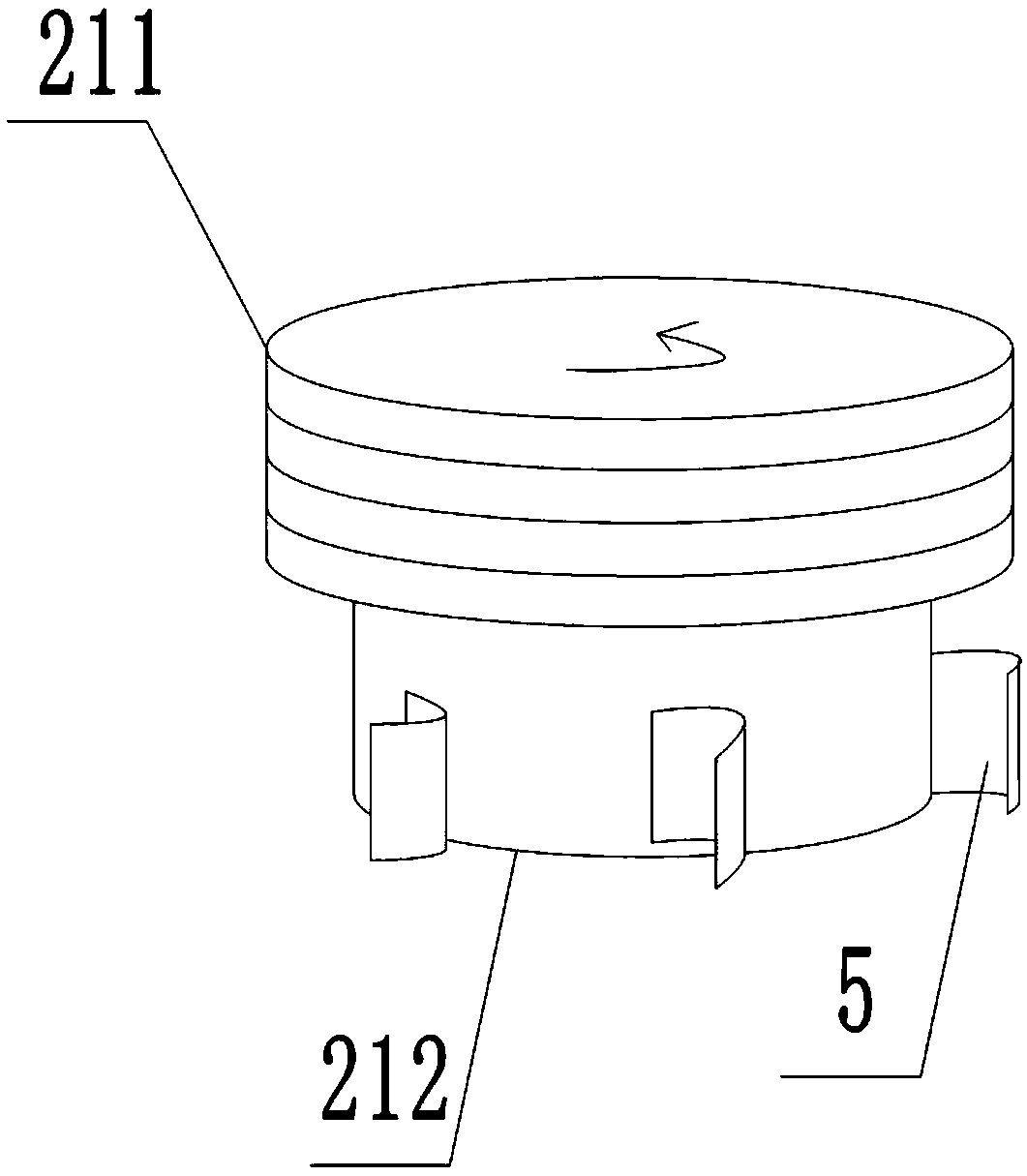
[0041] A device for artistic engraving, such as figure 1 , including a handle 1, a cutter head 2 and a chip removal pipe 3; Threaded in the threaded groove 11. like figure 2 and image 3 , the threaded rod 21 comprises a cylindrical threaded rod body 211 and a cylindrical end 212, the threaded rod body 211 is provided with external threads; the cylindrical end 212 is fixed on the lower end of the threaded rod body 211; and the diameter of the threaded rod body 211 greater than the diameter of the cylindrical end 212. An arc-shaped tab 5 is fixed on the circumference of the cylindrical end 212 .

[0042] In addition, in order to ensure that the cutter head 2 extends into the threaded groove 11, there is a larger space for air supply, and the depth of the threaded groove 11 is greater than or equal to the length of the threaded rod 21. Of course this can be set as required, when the depth of the threaded groove 1...

Embodiment 2

[0052] The difference between this embodiment and Embodiment 1 is that, if Figure 4 , Figure 5 and Image 6 , the cavity wall at the bottom of the air chamber 12 is provided with an arc-shaped mouth 6 and a folding telescopic layer 61, and the arc-shaped mouth 6 is sealed by a folding telescopic layer 61; The cut-off plate 62 passes through the folded telescopic layer 61 and is fixedly connected thereto. The outer wall of the cut-off plate 62 is in close contact with the wall of the wind chamber 12 , for example, if the wind chamber 12 is cylindrical, the cut-off plate 62 is arc-shaped to match the wall of the wind chamber 12 . The folding and stretching layer 61 in this solution is a corrugated rubber layer or a corrugated metal sheet layer.

[0053] During use, when the blowing holes 1241 on the rotating disk 124 do not correspond to the air outlet holes 123, the wind in the air chamber 12 will all enter into the air supply pipe 13, thereby realizing the tightening acti...


PUM


Abstract

The invention relates to the technical field of engraving, in particular to a device for artistic engraving. The device for artistic engraving comprises a cutter handle and a tool bit; a threaded rodis fixed to the tool bit; a threaded groove is formed in the end portion of the cutter handle, and the threaded rod is connected in the threaded groove in a threaded manner; a scrap removing pipe is further included; the cutter handle is internally provided with a wind cavity in which a fan is arranged; the lower portion of the wind cavity is provided with an air outflow hole, and the lower cavitywall of the wind cavity is rotationally connected with a rotating disk; the rotating disk is provided with air blowing holes; one end of the scrap removing pipe is fixed to the rotating disk, and theother end of the scrap removing pipe is provided with rotating blades and a grinding disk; the grinding disk is rotationally connected to the scrap removing pipe; the rotating blades are fixed to thegrinding disk; protruding blades are fixed to the end portion of the threaded rod in the circumferential direction; an air feeding pipe is further arranged in the cutter handle; and one end of the air feeding pipe communicates with the wind cavity, and the other end of the air feeding pipe is used for blowing air to the protruding blades. Due to the scheme, the problems that in the prior art, anengraving cutter cannot grind the side wall of an engraving gap after engraving, scraps in the engraving gap cannot be blown out in time, and the tool bit is prone to get loose in the engraving process are solved.

Description

technical field [0001] The invention relates to the technical field of engraving, in particular to an art engraving device. Background technique [0002] Carving is the cutting or carving of wood, stone, or other material into a desired shape. Tools that serve this purpose are knives, chisels, gouges, cones, hatchets, and hammers. In the most common method of carving, you hold a chisel in one hand and a mallet in the other, and use the mallet to drive the chisel into wood or stone. A carved finished work can be called an engraving, and engraving is usually used to refer to a work of serious artistic or aesthetic significance. [0003] At present, the more common engraving knives mainly include a cutter head and a handle, wherein the cutter head is fixed on the handle. When carving, different parts need to be carved, so different types and models of carving knives need to be prepared; users prepare many carving knives, which take up a lot of space, are inconvenient to stor...

Claims


Application Information

Patent Timeline
Patent Type & Authority Applications(China)
IPC IPC(8): B44B11/02B24B23/02B08B5/02
Inventor 欧阳婧芸何婉亭何明黄月朋宇姚雪儒
Owner CHONGQING IND POLYTECHNIC COLLEGE
Learn More